Convex lens focal length measuring device and method

A measuring device and a convex lens technology, applied in the field of convex lenses, can solve the problems of many optical elements, large influence of measurement results, complicated mechanism, etc., and achieve the effect of simple equipment and intuitive interference pattern.

Active Publication Date: 2014-10-22
SHANGHAI INST OF OPTICS & FINE MECHANICS CHINESE ACAD OF SCI
View PDF5 Cites 33 Cited by
  • Summary
  • Abstract
  • Description
  • Claims
  • Application Information

AI Technical Summary

Problems solved by technology

The measurement error of the long focal length based on the Talbotta effect of the Longji grating is 0.15%. However, this method has a comple

Method used


Image

  • Convex lens focal length measuring device and method
  • Convex lens focal length measuring device and method
  • Convex lens focal length measuring device and method

Examples


Embodiment 1

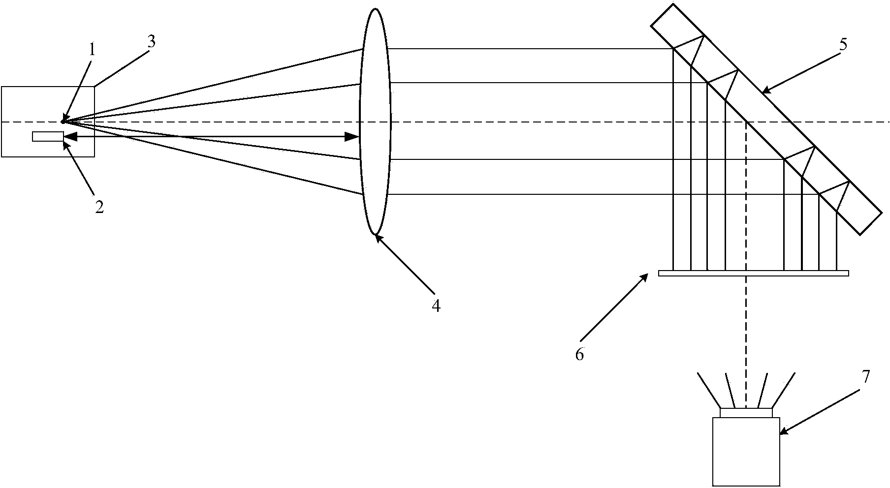
[0040] Such as figure 1 As shown: the convex lens focal length measuring device of the present invention is composed of 1053nm optical fiber point light source 1, laser range finder 2, precision moving guide rail 3, convex lens to be measured 4, shearing interference plate 5, ground glass screen 6 and CCD7:

[0041] The point light source 1 is an optical fiber point light source with a core diameter of 5.8 μm;

[0042] The optical fiber point light source 1 and the laser range finder 2 are installed on the same adjustment frame, and the adjustment frame has an overall lifting, pitching and left and right movement adjustment mechanism. The measurement zero point of the optical fiber point light source 1 and the laser rangefinder 2 is guaranteed to be in the same plane perpendicular to the optical axis of the lens to be measured.

[0043] The adjustment frame is fixed on the one-dimensional precision moving guide rail 3 for forward and backward translation, and the translation ...

Embodiment 2

[0061] Such as figure 1 As shown: the focal length measuring device of the convex lens of the present invention consists of a 1053nm point light source 1, a laser range finder 2, a precision moving guide rail 3, a convex lens to be measured 4, a shearing interference plate 5, a ground glass screen 6 and a CCD7:

[0062] The point light source 1 is an optical fiber point light source with a core diameter of 5.8 μm;

[0063] The optical fiber point light source 1 and the laser rangefinder 2 are installed on the same adjustment frame, which has an integral lifting, pitching and left and right movement adjustment mechanism. The measurement zero points of the optical fiber point light source 1 and the laser rangefinder 2 are guaranteed to be in the same plane perpendicular to the optical axis of the lens to be measured.

[0064] The adjustment frame is fixed on the one-dimensional precision moving guide rail 3 for forward and backward translation, and the translation direction is ...


PUM

PropertyMeasurementUnit
Core diameteraaaaaaaaaa
Diameteraaaaaaaaaa

Abstract

Disclosed is a convex lens focal length measuring device and method. The device is composed of a 1053 nm fiber point light source, a laser range finder, a precise moving guide rail, a convex lens to be measured, a shearing interference plate, a frosted glass screen and a CCD (charge coupled device). A user observes the fringe pattern formed on the shearing interference plate by output beams through the CCD after the lens is collimated, then adjusts the moving direction and the position of the fiber point light source on the precise moving guide rail, enables the 1053 nm point light source to finally be positioned on a focal plane, and then obtain the focal length of the lens through measurement of the laser range finder. The convex lens focal length measuring device has the advantages of being simple in structure, convenient to adjust and high in measuring precision and can help evaluate the optical quality of the convex lens through transverse shearing interference fringes generated during the measuring process to provide valuable detecting data for installation, calibration and optical manufacture of convex lenses.

Description

technical field [0001] The invention relates to a convex lens, in particular to a measuring device and a measuring method for the focal length of the convex lens. Background technique [0002] Usually, a high-power laser system is equipped with a large number of different caliber spatial filters and beam shrinking systems. The former is used to suppress nonlinear effects, improve the safe operation flux of the system, filter and cut off high-frequency information, and protect the laser working medium; the latter It is mostly used for beam imaging transmission and laser parameter measurement. The core optical elements of the spatial filter and beam reduction optical system are optical convex lenses with different apertures and focal lengths. The focal length and its optical quality are the most basic technical parameters of optical convex lenses. [0003] In order to measure the focal length of an optical convex lens, a variety of measurement techniques have been proposed, ...

Claims


Application Information

Patent Timeline
IPC IPC(8): G01M11/02
Inventor 朱海东郭爱林祝沛胡恒春唐仕旺马晓君谢兴龙
Owner SHANGHAI INST OF OPTICS & FINE MECHANICS CHINESE ACAD OF SCI
Why Eureka
Try Eureka