
Multi-frequency antenna

A multi-frequency antenna, low-frequency technology, applied to antennas, devices that make antennas work in different bands at the same time, electrical components, etc.

Inactive Publication Date: 2014-10-22
SHENZHEN FUTAIHONG PRECISION IND CO LTD +1
View PDF4 Cites 14 Cited by
  • Summary
  • Abstract
  • Description
  • Claims
  • Application Information

AI Technical Summary

Problems solved by technology

On the other hand, multi-band antennas are generally more complex in structure, but since the appearance of the antenna module tends to be thinner and miniaturized, the antenna design must also have the characteristics of miniaturization in addition to broadband

Method used


Image

  • Multi-frequency antenna
  • Multi-frequency antenna

Examples


Embodiment Construction

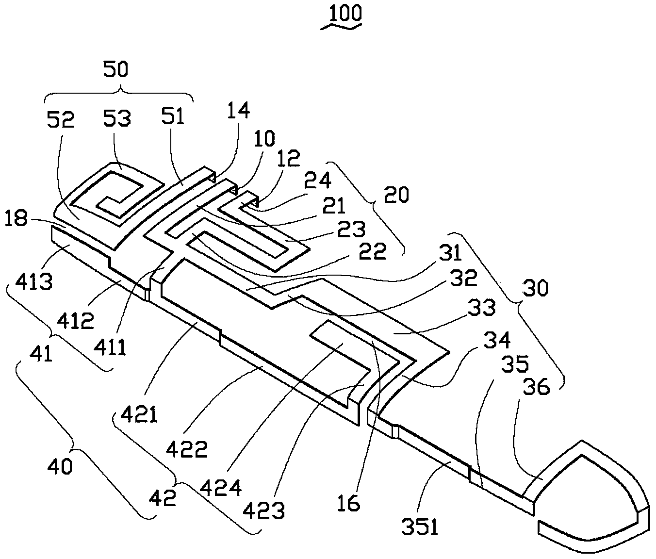
[0011] see figure 1 , the present invention provides a multi-frequency antenna 100, which is applied to mobile phones, tablet computers and other wireless communication devices (not shown in the figure) for sending and receiving wireless signals.

[0012] The multi-frequency antenna 100 of the preferred embodiment of the present invention includes a feed-in terminal 10, a first ground terminal 12, a second ground terminal 14, a loop microstrip line 20, a low-frequency resonance element 30, a high-frequency resonance element 40 and a parasitic microstrip line 50.

[0013] The feed-in terminal 10 is used to electrically connect with a signal feed-in point (not shown) on the circuit board of the wireless communication device, so as to feed current into the multi-frequency antenna 100 .

[0014] The loop microstrip line 20 is connected between the feeding end 10 and the first ground terminal 12, and the loop microstrip line 20 includes a first connection section 21, a second conn...


PUM


Abstract

The invention provides a multi-frequency antenna which comprises a feeding end, a first grounding end, a second grounding end, a loop microstrip line, a low-frequency resonant element, a high-frequency resonant element and a parasitic microstrip line. The loop microstrip line is connected between the feeding end and the first grounding end. The low-frequency resonant element and the high-frequency resonant element are connected to the loop microstrip line. The parasitic microstrip line is in electrical connection with the second grounding end. The high-frequency resonant element comprises a first open-circuit microstrip line and a second open-circuit microstrip line. The low-frequency resonant mode is excited by the low-frequency resonant element. The high-frequency resonant element is used to excite the high-frequency resonant mode. The second open-circuit microstrip line is coupled with the low-frequency resonant element to reduce the electrical characteristic length of the low-frequency resonant element. The parasitic microstrip line is coupled with the first open-circuit microstrip line to increase the bandwidth of the multi-frequency antenna on the high-frequency frequency band. The multi-frequency antenna has the advantage of small size and can be used to receive signals of multiple frequency bands.

Description

technical field [0001] The invention relates to a multi-frequency antenna, in particular to a multi-frequency antenna capable of receiving multiple frequency bands. Background technique [0002] In a wireless communication device, the antenna device used to transmit and receive radio waves to transmit and exchange radio data signals is undoubtedly one of the most important components in the wireless communication device. In recent years, various communication systems and applications using different operating frequency bands have emerged continuously, which makes the design of antennas develop towards multi-frequency antennas covering multiple system frequency bands. In order to ensure that the wireless communication device can transmit signals in various wireless communication systems using different operating frequency bands, the antenna device must be capable of transmitting and receiving signals of various frequencies. On the other hand, the structure of multi-band ante...

Claims


Application Information

Patent Timeline
Patent Type & Authority Applications(China)
IPC IPC(8): H01Q5/01H01Q5/10
Inventor 许倬纲林哲彦
Owner SHENZHEN FUTAIHONG PRECISION IND CO LTD
Learn More