

Combined type multi-tooth stator iron hybrid field switch flux motor
A technology of switched flux motor and multi-tooth stator, which is applied in the direction of electrical components, electromechanical devices, electric components, etc. It can solve the problems of difficult adjustment of excitation magnetic field, large output torque fluctuation, and difficulty in winding off the assembly line, so as to achieve easy heat dissipation, Good adaptability, weakening the effect of motor output torque ripple
- Summary
- Abstract
- Description
- Claims
- Application Information
AI Technical Summary
Problems solved by technology
Method used
Image

Examples
Embodiment Construction
[0022] The composition structure and electromagnetic performance of a combined multi-tooth stator core hybrid excitation switching flux motor of the present invention will be specifically introduced below in conjunction with the accompanying drawings:
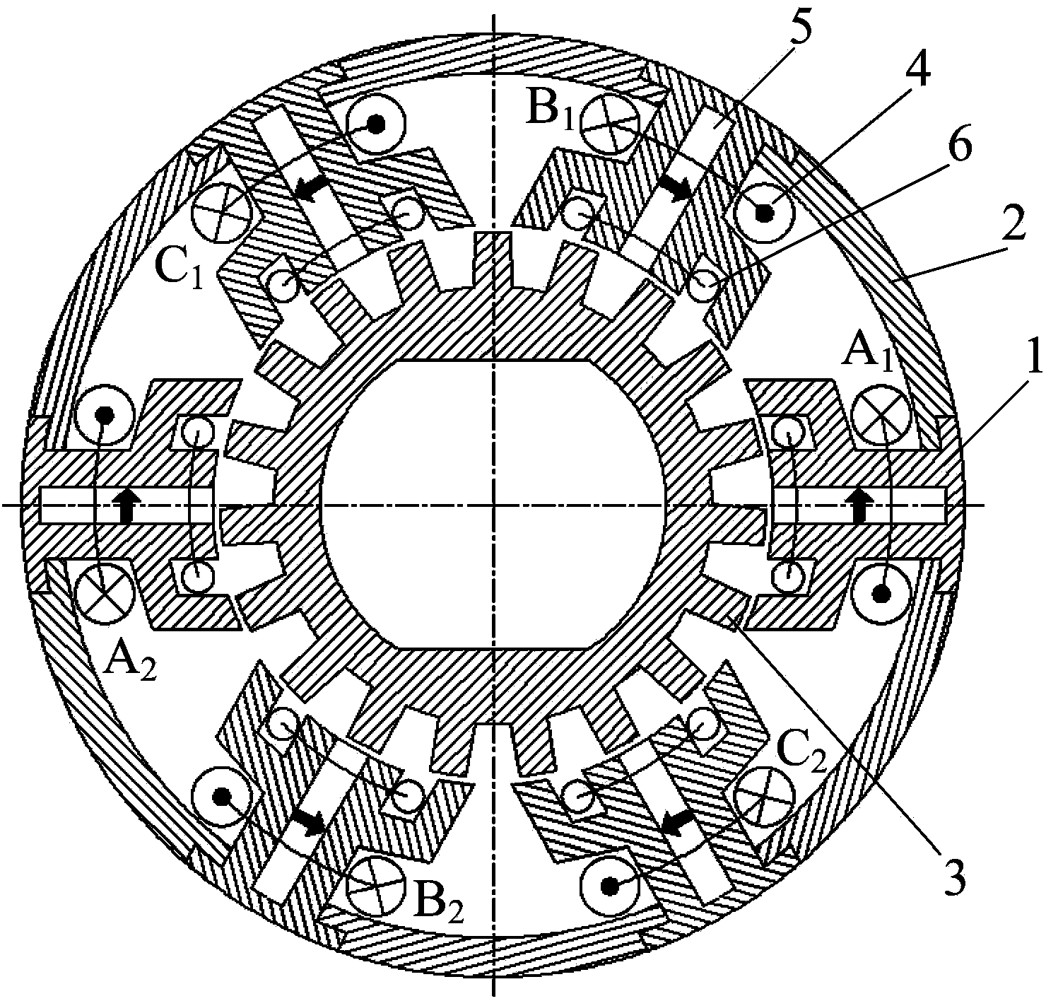
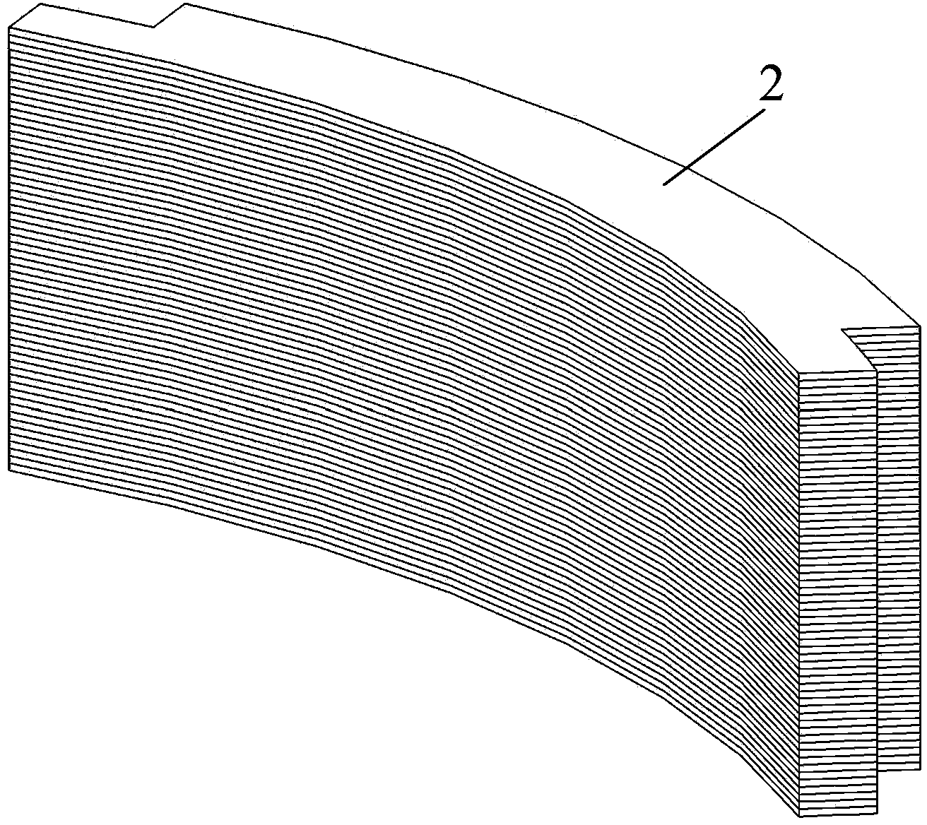
[0023] refer to figure 1 As shown, a combined multi-tooth stator core hybrid excitation switching flux motor of the present invention mainly consists of a stator core tooth module 1, a stator core yoke module 2, a rotor core 3, an armature winding 4, a magnetic steel 5, and an excitation Winding 6, motor frame 7, install magnetic isolation aluminum sleeve 9, aluminum sleeve end cover 10, motor shaft 12 etc. are formed.
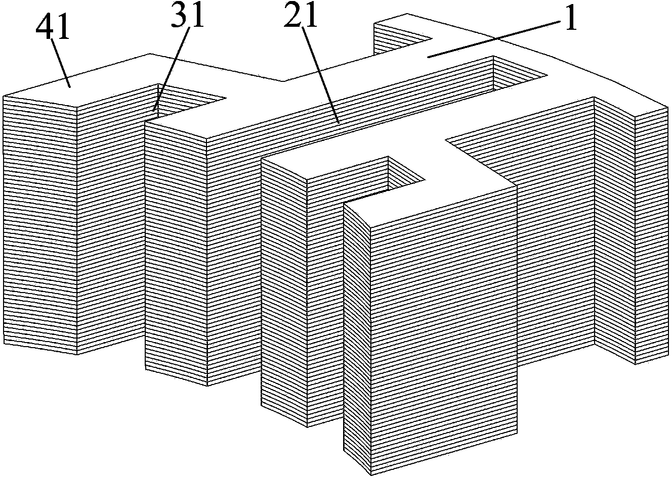
[0024] combine figure 1 and figure 2 As shown, the stator core tooth module 1 is a multi-tooth structure, and its center is coaxially provided with a slot 21, and the two sides of the slot are symmetrically provided with tooth slots 31, and the tooth slots 31 are adjacent ones. The space between stacked con...
PUM
 Abstract
Description
Claims
Application Information