Film residue recycling machine

A recycling machine and residual film technology, which is applied in the fields of collectors, agricultural machinery and implements, and applications, can solve the problems of difficult separation of crop rhizomes and residual film, increased separation and cleaning work, etc., and achieves considerable economic benefits and low recovery costs. , The effect of reducing the recovery time of residual film

Inactive Publication Date: 2014-10-29
单思诚
View PDF9 Cites 12 Cited by
  • Summary
  • Abstract
  • Description
  • Claims
  • Application Information

AI Technical Summary

Problems solved by technology

In the process of collecting residual film by the drum type residual film recycling machine, it is difficult to separate the soil, harvested crop roots and residual film, which adds great difficulty to the separation and cleaning work.

Method used


Image

  • Film residue recycling machine
  • Film residue recycling machine
  • Film residue recycling machine

Examples


Embodiment 1

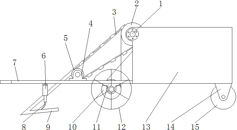
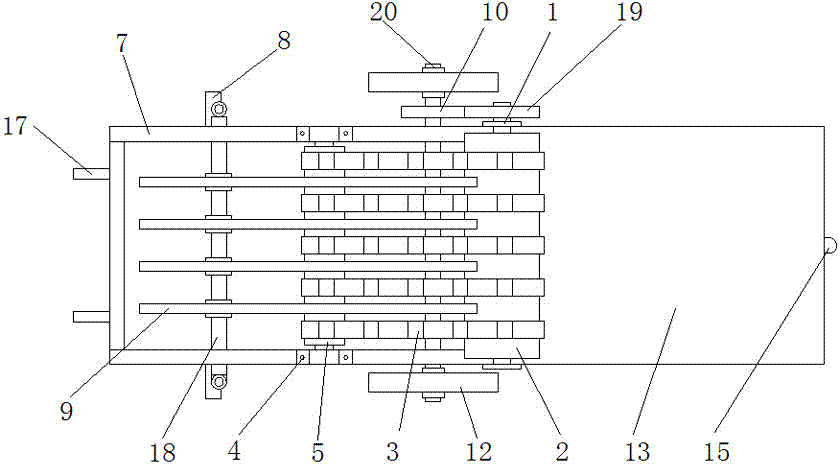
[0021] The walking direction of the device is the front end, that is, if figure 1 , 2 , 4, and 5 show the left side as the front end. Draw frame 17 is installed at the front end of frame 7, and this device links to each other with tractor by draw frame, drives its walking by tractor. Residual film collection box 13 is installed on the rear end of frame, and road wheel 12 is installed on frame both sides, and road wheel is fixedly installed on axle 20 two ends, and axle is installed on the frame by bearing block 11, as figure 2 As shown, a driving pulley 10 is fixedly installed on the upper side of the shaft;

[0022] A conveying device is installed on the frame between the residual film collection box and the traction frame. It forms a low front and high rear shape.

[0023] The driving wheel 2 is rotatably fixed on the residual film collecting box by the bearing fixing seats 1 on both sides of the residual film collecting box. The driven wheel is fixed by bearing blocks...

Embodiment 2

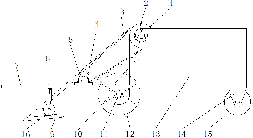
[0031] like image 3 As shown, on the basis of Embodiment 1, the soil removal shovel 8 is replaced with a disc-shaped film cutting knife 16, and the remaining film of all mulches in the farmland is cut to a set width by the film cutting knife, and then the remaining film is cut. Recycle. Simultaneously transmission chain is made up of the driving gear that is fixed on axle 20 upper side and the passive gear that is fixed on the fixed shaft upper side of fixed driving wheel 2, and driving leather gear and driven gear mesh with each other, drive driving wheel 2 rotations.

[0032] In the above embodiments, the spacing and quantity of the triangular film lifters 9 can be determined according to the width of the film. For increasing the frictional force of the strip conveyor belt 3, protrusions are evenly distributed on the strip conveyor belt.

[0033] In order to ensure the stability of the device in the walking process, a support wheel 15 is installed at the rear end of the f...


PUM


Abstract

The invention relates to agricultural equipment, in particular to a film residue recycling machine. A traction frame is installed at the front end of a machine frame of the film residue recycling machine. A film residue collecting box is installed at the rear end of the machine frame. Walking wheels are installed on the two sides of the machine frame and fixedly installed at the two ends of a shaft, and the shaft is fixedly installed on the machine frame through bearing pedestals (11). A transmission chain is fixedly installed on one side of the shaft. A conveying device is installed at the portion, between the film residue collecting box and the traction frame, of the machine frame. Three or more triangular film lifting devices are fixed below the portion, at the front end of the conveying device, of the machine frame in parallel, and the upper edges the film lifting devices are respectively arranged between two adjacent strip-shaped conveying belts. Soil spades or film cutters are installed at the portions, on the two sides of the film lifting devices, of the machine frame. The film residue recycling machine can recycle film residues remaining after whole-film mulching or half-film mulching and has the advantages of being simple in structure, small in mating power, low in recycling cost, high in one-time completely-recycling rate and the like.

Description

technical field [0001] The invention relates to an agricultural equipment, in particular to a residual film recovery machine. Background technique [0002] At present, the use of plastic film to cover planting in the agricultural planting process has been quite popular. It has many advantages, but it also brings many problems. The main reason is that the plastic film left in the farmland has caused serious environmental pollution. The film is very harmful to the growth of crops. [0003] At present, the main structural forms of residual film recovery machines are rake type, elastic tooth type, drum type, etc. The above types of residual film recovery machines generally have problems such as unclean collection and difficulty in centralized collection of residual film. For example, the rake-type residual film recovery machine and the spring-tooth type residual film recovery machine need to be collected 2-3 times repeatedly, and the collection rate can reach about 65%-75%. Dur...

Claims


Application Information

Patent Timeline
Patent Type & Authority Applications(China)
IPC IPC(8): A01B43/00
Inventor 单思诚
Owner 单思诚
Why Eureka
Try Eureka