

Method for machining ultra-large roller
A processing method and super-large technology, which is applied in the processing of super-large drums and large-scale drums, can solve the problems that the coaxiality of both ends of the drums cannot be guaranteed, the processing equipment and site requirements are low, and the processing equipment and site requirements are high. Achieve the effect of reducing processing input cost, reducing processing input, and lower requirements for processing sites
- Summary
- Abstract
- Description
- Claims
- Application Information
AI Technical Summary
Problems solved by technology
Method used
Image

Examples
Embodiment 1
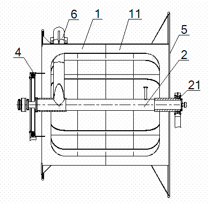
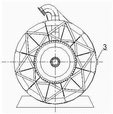
[0033] see figure 1 , figure 2 , a processing method for an ultra-large drum, the method comprises the following steps in turn:
[0034] Machining the drum shaft: using a vertical lathe to process the bearing mounting position 21 located at one end of the drum shaft 2;
[0035] Install the drum body: the drum body 1 includes a plurality of sub-cylinders 11 with equal diameters. When installing, first set a support ring inside the to-be-joined end of the sub-cylinders 11, and then set the adjacent sub-cylinders 11 on the drum Coaxial docking is performed after the outside of axis 2.
[0036] Welding reference block: Use a boring machine to weld the reference block 3 in the center of the side of the drum body 1. The upper and lower reference planes of the reference block 3 are arranged symmetrically with the center of the drum shaft 2. The vertical reference plane of the reference block 3 is aligned with the upper and lower reference blocks. Datum vertical setting;
[0037]...
PUM
 Abstract
Description
Claims
Application Information