Novel pipe fitting cutting and chamfering machine

A technology of chamfering machine and cutting mechanism, which is applied in the direction of metal processing, etc., can solve the problems of complex structure, many flying chips, high noise, etc., and achieve the effect of less energy consumption, less failure rate, and no powder chips

Inactive Publication Date: 2014-10-29
GUANGDONG LIANSU MACHINERY MFG
View PDF9 Cites 8 Cited by
  • Summary
  • Abstract
  • Description
  • Claims
  • Application Information

AI Technical Summary

Problems solved by technology

[0003] The technical problem to be solved by the present invention is to provide a new type of pipe cutting and chamfering machine, which can solve the problems of large noise, excessive flying debris, energy consumption, and complex structure caused by the traditional cutting machine using saw blade chamfering.

Method used


Image

  • Novel pipe fitting cutting and chamfering machine
  • Novel pipe fitting cutting and chamfering machine

Examples


Embodiment

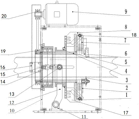
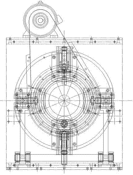
[0021] like figure 1 and figure 2 As shown, a novel pipe cutting and chamfering machine is used for cutting high-calcium pipes, including a frame 10, a rotating disk 5 arranged on the frame, a cutting mechanism, a clamping mechanism and a driving device, and the rotating disk 5 is formed by The driving device controls the rotation, and the cutting mechanism includes a rocker arm base 11 arranged on the frame 10, a rocker arm 12 connected with the rocker arm base 11, a pusher shaft 13 connected with the rocker arm 12, and a pusher shaft 13 connected with the rocker shaft 13. The pusher disc 4, the pusher shaft 13 is controlled to slide by the cylinder 16, specifically the cylinder 16 is connected with the pusher shaft 13 through the floating joint 15 and the cylinder joint 14 in turn, and the pusher disc 4 is provided with a push-up Knife arm and lower pusher arm, described upper and lower pusher arms are all provided with chute, and described upper pusher arm 8 is connected ...


PUM


Abstract

The invention discloses a novel pipe fitting cutting and chamfering machine which comprises a machine frame and a cutting mechanism arranged on the machine frame. The cutting mechanism comprises a rocker arm base arranged on the machine frame, a rocker arm connected with the rocker arm base, a push broach shaft connected with the rocker arm, and a push broach plate connected with the push broach shaft. The push broach shaft is controlled by a cylinder to slide. A push broach arm is arranged on the push broach plate and provided with a slide groove. The push broach arm is connected with a tool installation base. The tool installation base is provided with a slide block correspondingly sliding in the slide groove, and is provided with a sawtooth-free tool. The novel pipe fitting cutting and chamfering machine is simple in structure, low in energy consumption and environmentally friendly.

Description

technical field [0001] The invention belongs to the field of pipe processing, in particular to a novel pipe cutting and chamfering machine. Background technique [0002] At present, the cutting and chamfering of many PVC pipes in China are in the form of planetary cutting machine saw blade cutting and chamfering machines, because the saw blade cutting and chamfering method is often complex in structure and requires a motor to drive the saw blade to rotate the saw blade at high speed On the one hand, the cutting machine is noisy and has a lot of flying chips; on the other hand, when chamfering, it is necessary to repeatedly adjust the pressing distance between the eccentric wheel and the surface of the pipe, the operation is extremely cumbersome, and the debugging level of the debugging personnel is very high; and , the feeding structure needs to be suppressed by hydraulic pressure, and the failure rate is high; at the same time, the way of cutting and chamfering the saw blad...

Claims


Application Information

Patent Timeline
IPC IPC(8): B26D1/12B26D5/08
Inventor 黄正雄陈瑜杨敬成
Owner GUANGDONG LIANSU MACHINERY MFG
Why Eureka
Try Eureka