Tilting type continuous acrylic cracking furnace

A tilting, acrylic technology, applied in the preparation of organic compounds, chemical instruments and methods, organic chemistry, etc., can solve the problems of easily damaged cracking kettle, uneven heating, hidden safety hazards, etc., to improve production efficiency and save manpower. Effect

Active Publication Date: 2014-10-29
宝鸡市晋旺达机械设备有限公司
View PDF6 Cites 4 Cited by
  • Summary
  • Abstract
  • Description
  • Claims
  • Application Information

AI Technical Summary

Problems solved by technology

The existing cracking equipment is intermittent cracking. The waste acrylic is directly put into the cracking tank heated by an open flame for cracking. The material is piled up in the tank and contacts the wall of the cracking tank. Due to uneven heating, the cracking temperature cannot be accurately controlled, and the quality of the finished product is poor. The recovery rate is low, the waste is large, the pyrolysis kettle is easy to scale and coke, and the lid of the pyrolysis kettle needs to be opened when cleaning, and the coke is manually shoveled, which is difficult to clean and labor-intensive, and the cracking kettle is easy to be damaged by manual coke cleaning, and remains in the kettle during coke cleaning The emission of exhaust gas can easily cause environmental pollution and the disorderly diffusion of flammable and explosive gases, posing serious safety hazards
In addition, due to intermittent production, labor efficiency is low, and cracking a certain amount of waste and old organic glass often requires many cracking kettles, which occupy a large area and are inefficient. Therefore, it is necessary to propose an improvement

Method used


Image

  • Tilting type continuous acrylic cracking furnace
  • Tilting type continuous acrylic cracking furnace
  • Tilting type continuous acrylic cracking furnace

Examples


Embodiment Construction

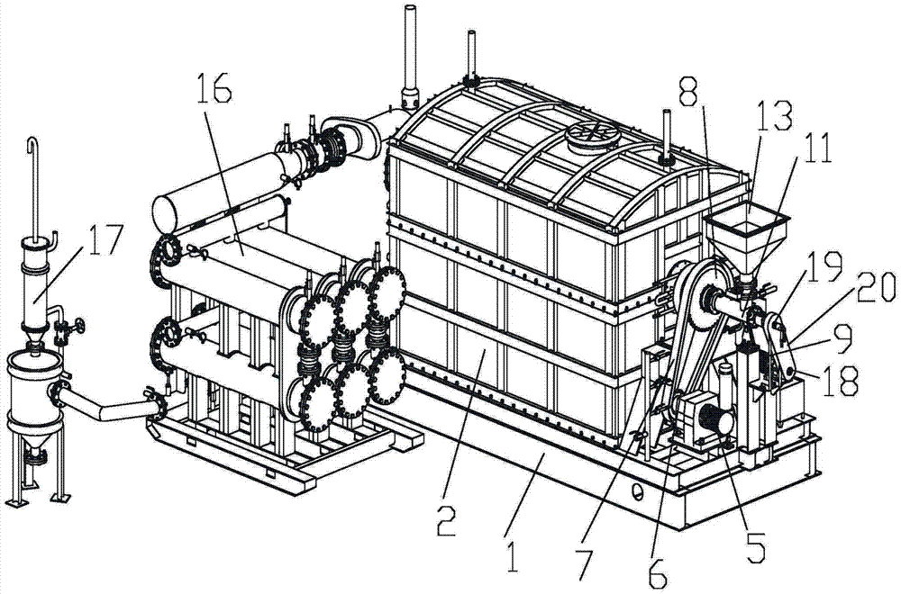
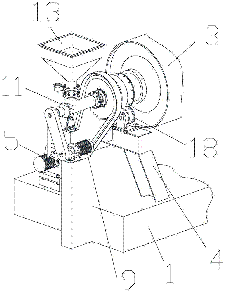
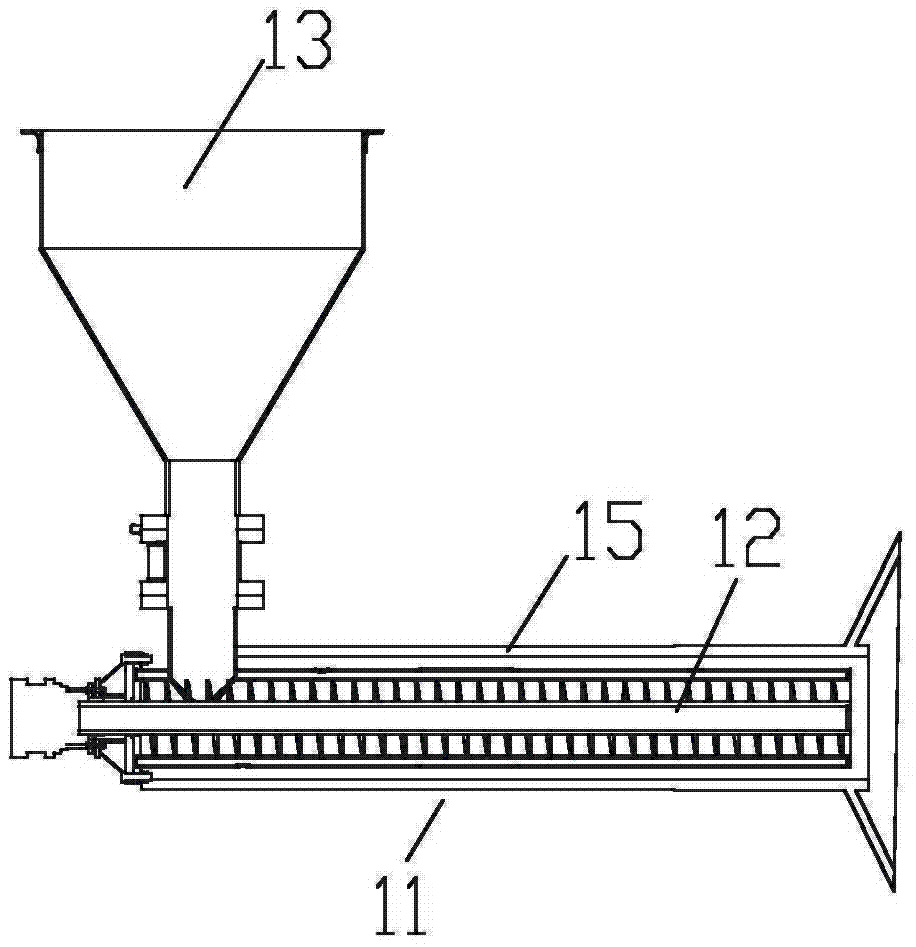
[0021] Attached below Figure 1-6 An embodiment of the present invention is described.

[0022] The tilting continuous acrylic cracking furnace has a base 1, and the upper end surface of the base 1 is provided with a tilting platform. Specifically, the tilting platform includes a jacking platform 2 and a jacking hydraulic cylinder 10. The bottom end of the jacking platform 2 is connected to the One side of the upper end surface of the base 1 is hinged, and the other side of the upper end surface of the base 1 is provided with a jacking hydraulic cylinder 10 , and the piston rod of the jacking hydraulic cylinder 10 telescopically lifts or lowers the other end of the bottom of the jacking platform 2 . A furnace body 2 is arranged on the tilting platform, and a drum 3 is arranged in the furnace body 2, and the support shafts at both ends of the drum 3 are supported on the support frames 4 at the two outer ends of the furnace body 2 through rollers 18, and the output shaft of the ...


PUM


Abstract

The invention provides a tilting type continuous acrylic cracking furnace which is characterized in that a tilting type platform is arranged on the upper end surface of a base; a furnace body is arranged on the tilting type platform; a drum is arranged in the furnace body and supporting shafts at two ends of the drum are supported on supporting frames at two outer ends of the furnace body through roller wheels; a driving chain wheel I is arranged on an output shaft of a driving motor I and drives a driven chain wheel I arranged on a supporting shaft at one end of the drum through a chain I; a driving chain wheel II is arranged on an output shaft of a driving motor II; a driven chain wheel II is arranged at one end of a water-cooling type spiral feeding device; the driving chain wheel II drives a driven chain wheel II through a chain II; the lower end of a feeding hopper is hermetically communicated with one end of the water-cooling type spiral feeding device; the other end of the water-cooling spiral feeding device is dynamically sealed with the supporting shafts of the drum and is communicated with the inlet end of the drum; the outlet end of the drum is communicated with the inlet end of a primary condensation device; the outlet end of the primary condensation device is communicated with the inlet end of a secondary condensation device; a liquid outlet of the secondary condensation device is communicated with a container tank. According to the tilting type continuous acrylic cracking furnace, continuous feeding and continuous heating cracking can be achieved, residual gas is fully condensed and residues on the inner wall of the drum can be easily removed. The tilting type continuous acrylic cracking furnace has relatively high practical values.

Description

technical field [0001] The invention belongs to the technical field of acrylic cracking regeneration equipment, and in particular relates to a tilting continuous acrylic cracking furnace. Background technique [0002] Acrylic is widely used in various industries, and using waste acrylic cracking and regeneration to obtain methyl methacrylate monomer to realize the recycling of acrylic is in line with the policy of circular economy and has good economic and social benefits. a faster development. The existing cracking equipment is intermittent cracking. The waste acrylic is directly put into the cracking tank heated by an open flame for cracking. The material is piled up in the tank and contacts the wall of the cracking tank. Due to uneven heating, the cracking temperature cannot be accurately controlled, and the quality of the finished product is poor. The recovery rate is low, the waste is large, the pyrolysis kettle is easy to scale and coke, and the lid of the pyrolysis k...

Claims


Application Information

Patent Timeline
Patent Type & Authority Applications(China)
IPC IPC(8): C07C67/333C07C69/54
CPCC07C67/333C07C69/54
Inventor 关珍旺郭云奇张国庆关越
Owner 宝鸡市晋旺达机械设备有限公司
Why Eureka
Try Eureka