An automatic handling machine that can adapt to the transportation of plates of different thicknesses
A technology that adapts to different handling machines. It is applied in the direction of conveyor objects, transportation and packaging, chemical instruments and methods, etc. It can solve the problems of wasting manpower, low work efficiency, and material jams, so as to improve the degree of cleaning, prevent material jams, The effect of improving machining accuracy
- Summary
- Abstract
- Description
- Claims
- Application Information
AI Technical Summary
Problems solved by technology
Method used
Image
Examples
Embodiment 1
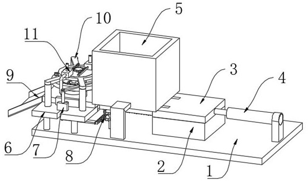
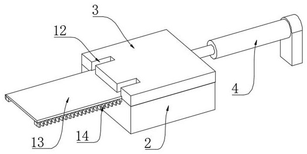
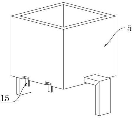
[0028] see Figure 2-Figure 3 , an automatic handling machine that can adapt to the transportation of plates of different thicknesses, including an installation base plate 1, a slide seat 2 is fixedly installed on the top right side of the installation base plate 1, and a slide plate 3 is slidably connected to the top of the slide base plate 2, and the top of the installation base plate 1 is opposite to the slide plate The right side wall of 3 is fixedly equipped with hydraulic cylinder 4, and the left side wall of slide plate 3 is fixedly connected with receiving plate 13, and the distance between the upper surface of receiving plate 13 and the upper surface of sliding plate 3 is lower than the thickness of the plate, and the front and rear sides of receiving plate 13 The side walls are fixedly connected with a rack 14, and the left side of the upper surface of the slide plate 3 is provided with two sets of vertically arranged material shifting grooves 12, and the top of the i...
Embodiment 2
[0031] see Figure 4, is basically the same as Embodiment 1, and a step further is that a processing table 6 is fixedly installed on the left side of the top of the installation base plate 1 relative to the material storage housing 5, and a groove 21 is provided in the middle of the upper surface of the processing table 6 for processing. A discharge plate 9 is fixedly connected to the left side wall of the platform 6 relative to the groove 21 , and the depth of the groove 21 is the same as the thickness of the receiving plate 13 .
[0032] When the next group of plates is pushed to the top of the processing table 6, the last plate will be pushed to the cavity of the discharge plate 9 for subsequent processing.
[0033] see Figure 5 , the front and rear sides of the top of the processing table 6 are movably connected to the limit mechanism 7, the limit mechanism 7 includes a slider 19, the bottom of the slider 19 is slidably connected to the top of the processing table 6, and...
Embodiment 3
[0043] see Figure 8 , is basically the same as Embodiment 2, and one step closer is that the inner chamber of the jet housing 34 is fixedly connected with an air bag 36 on the side wall away from the piston plate 35, and the inner chamber of the air bag 36 is connected with a spring 2 37 transversely, and the inner chamber of the air bag 36 The top is fixedly connected with a liquid inlet pipe-38, and the inner chamber of the liquid inlet pipe-38 is provided with a one-way valve connected from top to bottom. There is a disinfectant tank outside the top of the liquid inlet pipe-38. 39 liquid inlet positions are communicated.
[0044] The air pressure in the inner cavity of the jet casing 34 will enter the nozzle 44 and press the valve core 41 downward, and at the same time compress the spring 3 42, so that the valve core 41 is separated from the air inlet of the communication pipe 43, and the compressed gas enters the interior of the communication pipe 43 At this time, the di...
PUM
 Abstract
Description
Claims
Application Information
 - R&D
- Intellectual Property
- Life Sciences
- Materials
- Tech Scout
- Unparalleled Data Quality
- Higher Quality Content
- 60% Fewer Hallucinations
Browse by: Latest US Patents, China's latest patents, Technical Efficacy Thesaurus, Application Domain, Technology Topic, Popular Technical Reports.
© 2025 PatSnap. All rights reserved.Legal|Privacy policy|Modern Slavery Act Transparency Statement|Sitemap|About US| Contact US: help@patsnap.com


