Automatic test data positioning system and method for pavement condition

A technology of automatic detection and data positioning, applied in the directions of roads, roads, and road repair, etc., it can solve the problems of uncertain position of abscissa, losing the meaning of guiding road safety and maintenance, and not strictly determining statistical value of longitudinal coordinate, etc. The effect of precision

Active Publication Date: 2014-10-29
TECH TRANSFER CENT CO LTD NANJING UNIV OF SCI & TECH
View PDF5 Cites 17 Cited by
  • Summary
  • Abstract
  • Description
  • Claims
  • Application Information

AI Technical Summary

Problems solved by technology

Pavement defects processed according to the vehicle coordinates cannot be easily found according to the pile number, which loses the significance of guiding road safety and maintenance
[0005] Although the GPS marking method, the mileage pile insertion correction mileage method, and even the coding and labeling method along the road have been used in the prior art, they have not effectively solved the above problems.
In particular, the side-to-side swing of the detection vehicle’s trajectory makes the abscissa position of the detection data more uncertain. Therefore, the data position obtained by the existing vehicle-mounted automatic detection equipment is not only not strictly determined in the longitudinal coordinate but only has the statistical value of the road section, and the abscissa position is more uncertain. Therefore, a definite three-dimensional pavement and strict three-dimensional disease distribution cannot be obtained

Method used


Image

  • Automatic test data positioning system and method for pavement condition
  • Automatic test data positioning system and method for pavement condition

Examples


Embodiment Construction

[0040] In order to better understand the technical content of the present invention, specific embodiments are given together with the attached drawings for description as follows.

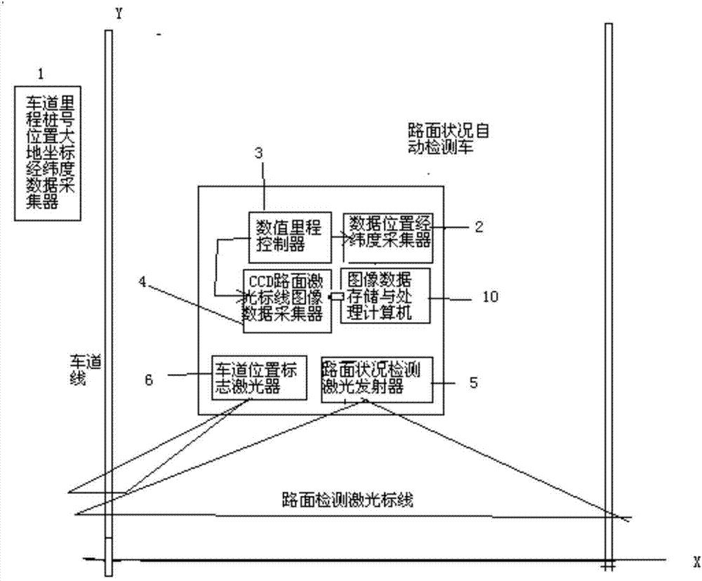
[0041] Such as figure 1 Shown is the system architecture of the automatic road condition detection data positioning system according to an embodiment of the present invention, wherein a road surface condition automatic detection data positioning system includes:

[0042] A lane mileage stake number position longitude and latitude collector 1, used to collect the latitude and longitude of each stake number position of the lane mileage stake, forming a mileage stake number-longitude and latitude electronic map database;

[0043] A first laser emitter 5, which is used to emit laser lines to the road surface to be tested, so as to form a section laser detection marking line on the road surface;

[0044] A second laser emitter 6 is used to emit a laser line to the lane line of the road surface to be me...


PUM


Abstract

The invention provides an automatic test data positioning system and method for a pavement condition. The method comprises the following steps of: acquiring longitude and latitude of each pile number position of each lane mileage pile by utilizing a longitude-latitude acquisition device to form a mileage-pile pile number-longitude and latitude electronic map database; controlling the acquisition of pavement fracture surface laser making line images and the longitude and latitude of the positions by utilizing a vehicle-mounted numerical value speedometer to automatically acquire vehicle track mileages and geodetic coordinate longitude and latitude of vehicle-mounted data points; performing longitude and latitude correlation on a certain vehicle-mounted data point position according to the longitude and latitude of the vehicle-mounted data points, the traveling track mileages and the mileage-pile pile number-longitude and latitude electronic map database which are synchronously acquired; determining a pile number position of the certain vehicle-mounted data point, namely a lane Y coordinate value; acquiring a horizontal coordinate zero point and an X coordinate value of the data through lane marking laser making lines and fracture surface laser making lines. The influence on non-linear lines and lateral oscillation of vehicle tracks during test is avoided, and the data of the position of lane marks can be strictly and certainly expressed.

Description

technical field [0001] The invention relates to the technical field of road surface state detection, in particular to a road surface state automatic detection data positioning system and a positioning method. Background technique [0002] How to determine the position of vehicles, personnel or road signs, and diseases on the long highway, the most traditional method is also the most common-sense method is to set mileage piles along the road, so that the road is set to determine the starting point as a zero point. dimensional coordinates, as long as the mileage coordinates of the target on the road are given, the exact road position of the target can be determined, and anyone can easily find it. [0003] As pavement facilities, signs or static detection of disease location is convenient and well-known. Although the development of modern satellite positioning technology has established more scientific and strict geodetic coordinates, using the latitude and longitude of the ta...

Claims


Application Information

Patent Timeline
Patent Type & Authority Applications(China)
IPC IPC(8): E01C23/01
Inventor 贺安之贺宁贺斌
Owner TECH TRANSFER CENT CO LTD NANJING UNIV OF SCI & TECH
Why Eureka
Try Eureka