Water-saving regulating valve

A technology of regulating valve and regulating rod, which is applied in the field of regulating valve, can solve the problem of inapplicability of reverse osmosis process, etc., and achieve the effect of simple structure and light volume

Active Publication Date: 2014-10-29
BEIJING ORIGIN WATER PURETECH CO LTD
View PDF8 Cites 1 Cited by
  • Summary
  • Abstract
  • Description
  • Claims
  • Application Information

AI Technical Summary

Problems solved by technology

However, this water saving valve is no

Method used


Image

  • Water-saving regulating valve
  • Water-saving regulating valve
  • Water-saving regulating valve

Examples


Embodiment 1

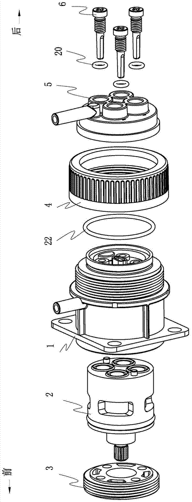
[0049] Such as figure 1 The water-saving regulating valve shown includes a valve body 1 , a valve core 2 , a compression cover 3 , an adjustment cover 5 , a compression cap 4 and three adjustment rods 6 . The valve core 2 is embedded in the valve body 1 . The compression cover 3 has a hollow part, which is set outside the boss at the front end of the valve core 2. The external thread on the compression cover 3 cooperates with the internal thread at the front end of the valve body 1 to fix the valve core 2 on the valve body 1. internal. The adjustment cover 5 is inserted from the front end of the compression cap 4, so that the water outlet 14 protrudes from the rear end of the compression cap 4, and the internal thread of the compression cap 4 cooperates with the external thread of the rear end of the valve body 1, so that the adjustment cover 5 Connect with the rear end of the valve body 1, and confirm that each valve body water outlet 12 is docked with the adjustment rod in...


PUM


Abstract

The invention provides a water-saving regulating valve which comprises a valve body 1, a valve element 2, a compressing cover 3, a compressing cap 4, a regulating cover 5 and a regulating rod 6. A water passage is arranged in the middle of the valve element, a water inlet groove is formed in the side face of the valve element, a water outlet is formed in the end face of the valve element, and a water outlet blocking piece is arranged in the middle of the water outlet. A water inlet is formed in the side face of the valve body. A water outlet is formed in the side face of the regulating cover, a regulating rod inserting hole is formed in the end face of the regulating cover, and the regulating rod inserting hole is in butt joint with the water outlet of the regulating cover, and is used for allowing the regulating rod to be inserted. An inward concave regulating rod water tank is formed in one end of the regulating rod, and has the function of limiting flow. After the regulating rod is inserted into the regulating rod inserting hole, the regulating rod water tank is communicated with a water outlet of the valve body. The size of a water outlet channel is changed by changing the depth of threads of the regulating rod entering the regulating rod inserting hole, and therefore the water flow strength is changed.

Description

【Technical field】 [0001] The invention relates to a regulating valve, in particular to a water-saving regulating valve. 【Background technique】 [0002] The purity obtained through the reverse osmosis process is to apply pressure on the raw water end and pass through the reverse osmosis membrane, so that water molecules and smaller molecular salts pass through the semi-permeable membrane to generate clean water, while the polluted components are concentrated into concentrated water. In actual application, the concentrated water (wastewater) will be drained, and the raw water will continue to be supplied to keep the pressure in the system constant. This working mechanism determines that the reverse osmosis process will discharge a large amount of wastewater, whether it is a small household water purifier or an industrial water purification system, the water consumption is huge. [0003] In order to reduce costs, CN102797871A discloses an intelligent water-saving valve assembl...

Claims


Application Information

Patent Timeline
IPC IPC(8): F16K11/06
CPCF16K3/314F16K3/32F16K11/074F16K27/045
Inventor 戴开跃鲁纯梁辉
Owner BEIJING ORIGIN WATER PURETECH CO LTD
Why Eureka
Try Eureka