Solar simulator

A technology for solar simulators and light-emitting lamps, applied in the field of solar simulators, can solve the problems of difficulty in reducing the unevenness of irradiation and the cumbersome setting of mesh filters, etc., and achieve the goal of reducing unevenness of irradiation, simple structure, and simple adjustment Effect

Inactive Publication Date: 2014-10-29
KYOSHIN ELECTRIC
View PDF1 Cites 2 Cited by
  • Summary
  • Abstract
  • Description
  • Claims
  • Application Information

AI Technical Summary

Problems solved by technology

[0008] However, although it is theoretically possible to configure such a filter unit, it is very troublesome to install a mesh filter on the area corresponding to the part with high irradiance on the solar panel.
For example, when the light-emitting state of a light-emitting lamp changes over time, e

Method used


Image

  • Solar simulator
  • Solar simulator
  • Solar simulator

Examples


Embodiment Construction

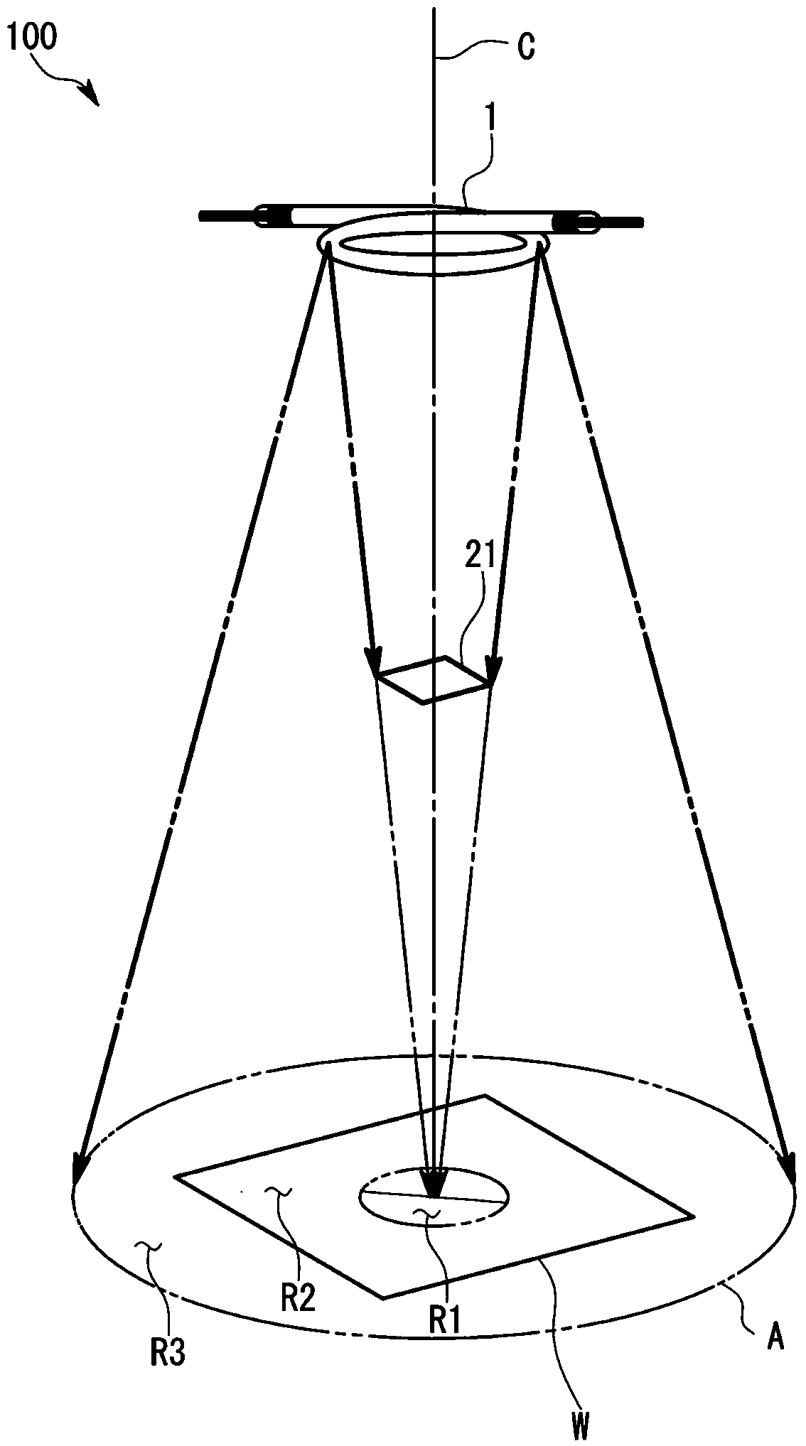
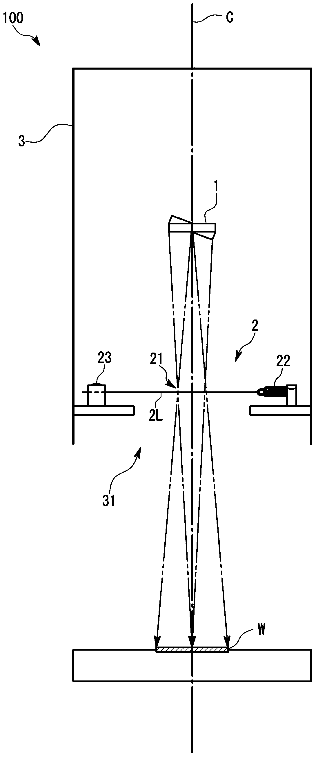
[0038] refer to Figure 1 to Figure 5 The solar simulator 100 according to the first embodiment of the present invention and the solar cell evaluation device 200 using the solar simulator 100 will be described.

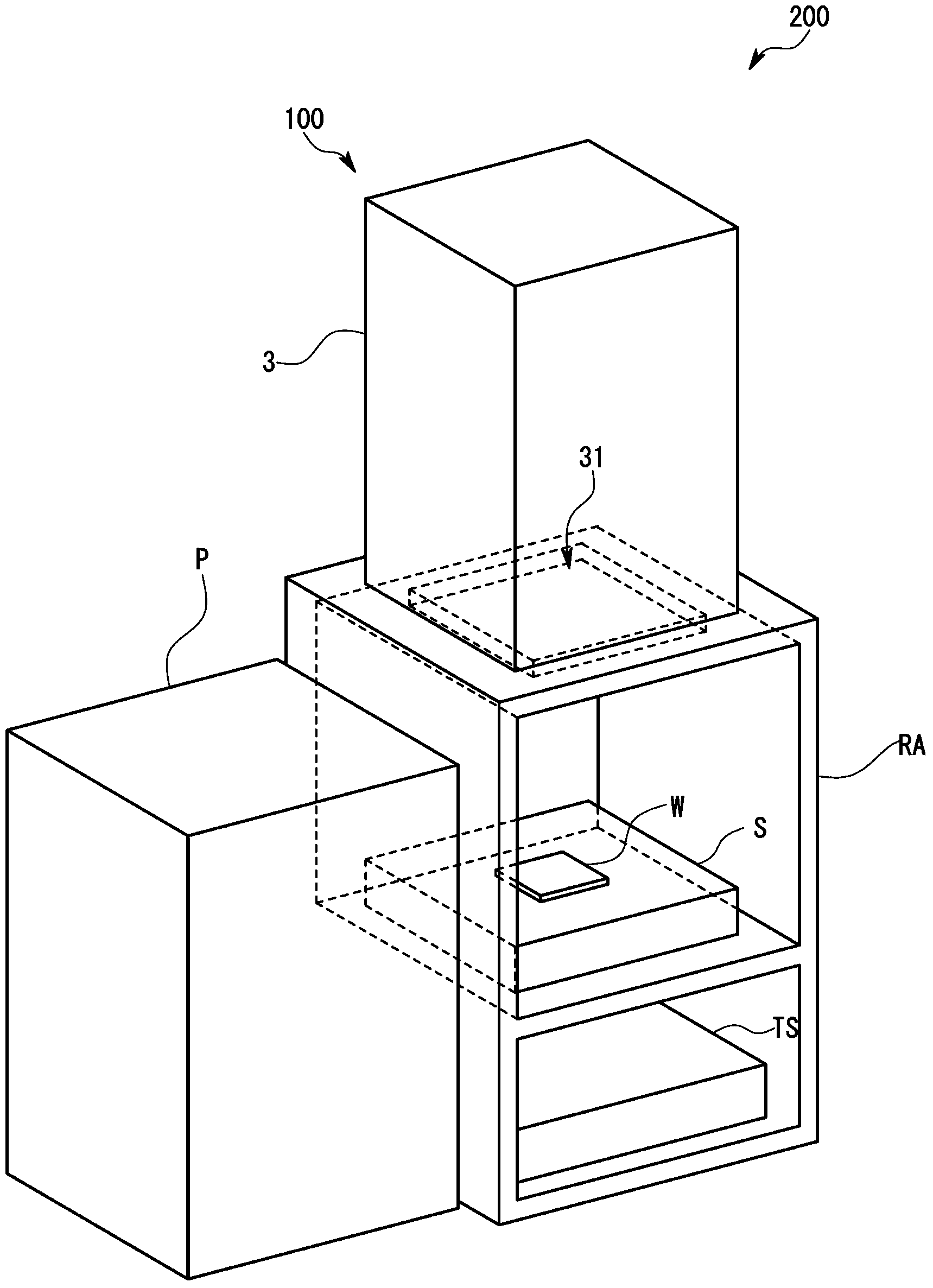
[0039] figure 1 The solar battery cell evaluation apparatus 200 of the first embodiment shown is used, for example, to evaluate output characteristics of solar battery cells W in a manufacturing stage, and to classify solar battery cells W according to characteristics.

[0040] The solar cell unit evaluation device 200 is as figure 1 As shown, it includes: a solar simulator 100 in a roughly cuboid shape, which irradiates pulsed light to a solar battery unit W as an irradiation object and as a workpiece; W; I-V tester TS, which measures the voltage value and current value output from the solar battery unit W, thereby measuring and evaluating the I-V characteristics; and lighting power supply P, which controls the lighting timing and lighting of the solar simulator 10...


PUM


Abstract

Theinvention provides a solar simulatorwhich is simple in structure and can greatly reduce irradiation unevenness of an irradiation object, for example, the solar simulator can satisfy supreme grade standard. The solar simulatorcomprises a luminescent lamp (1) in an annular shape, a workpiece (W) used as the irradiation object is configured on a cut-through direction of a ring, and an annular shielding body (21) which is formed by wire rods and is disposed between the luminescent lamp (1) and the workpiece (W).

Description

technical field [0001] The present invention relates to a solar simulator used for performance evaluation of solar battery cells and other light resistance environment evaluations. Background technique [0002] For example, in performance evaluation of a solar battery cell, JIS C8912 and IEC60904-9 define standards for the unevenness of irradiation of light irradiated on the surface of a solar battery cell to be irradiated. More specifically, the irradiance non-uniformity (irradiance unevenness due to different positions) is defined by the following formula. [0003] (Formula 1) [0004] ΔE = ± E max - E mim E max + E min × 100 [0005] Among them, ΔE: irra...

Claims


Application Information

Patent Timeline
IPC IPC(8): F21S2/00F21V1/00
CPCF21S8/006Y02E10/50H02S50/15
Inventor 镰谷幸平下埜彰夫
Owner KYOSHIN ELECTRIC
Why Eureka
Try Eureka