Measuring device for measuring vortex light beam high-order topological charge

A technology of vortex beams and measuring devices, applied in the direction of instruments, etc., can solve the problems of small topological charges, difficulty in meeting application requirements, small measurement range of high-order topological charges, etc.

Inactive Publication Date: 2014-10-29
HENAN UNIV OF SCI & TECH
View PDF2 Cites 37 Cited by
  • Summary
  • Abstract
  • Description
  • Claims
  • Application Information

AI Technical Summary

Problems solved by technology

The topological charge values ​​measured by these methods are simple and easy to operate, but the measurement range of high-order topological charges is small, and sometimes it is difficult to meet the application requirements.
[0003] It can be seen from the analysis that in the existing publ

Method used


Image

  • Measuring device for measuring vortex light beam high-order topological charge
  • Measuring device for measuring vortex light beam high-order topological charge
  • Measuring device for measuring vortex light beam high-order topological charge

Examples


Embodiment Construction

[0032] specific implementation plan

[0033] Below in conjunction with example the present invention will be further described.

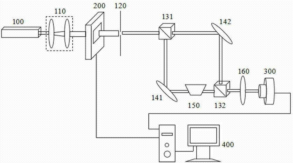
[0034] As shown in the figure, the present invention is a measuring device for measuring the high-order topological charge of a vortex beam. It is provided with a He-Ne laser 100 with a wavelength of 632.8nm. Collimated beam expander 110, spatial light modulator 200 written in fork-shaped computational hologram, generating vortex beam ; Then through the circular aperture diaphragm 120, the polarization fractionator 131; via polarization fractionator After 131, Vortex Beam transmitted vortex and reflected vortex light , reflected vortex light with transmitted vortex light into 90 o included angle, reflected vortex light mirror After 141, the dove prism 150 is used as the mirror image beam of the vortex beam and enters the polarization fractionator 132 in; transmitted vortex light mirror After 142, as a vortex beam Inj...


PUM


Abstract

A measuring device for measuring vortex light beam high-order topological charge is provide with a He-Ne laser device, wherein collimation and beam expanding devices are sequentially arranged in the light beam advancing direction of the laser device, a spatial light modulator where a forked phase hologram generated by a computer is input generates vortex light beams (shown in the description), and then the vortex light beams pass through a round hole diaphragm and a polarization beam splitter (shown in the description). The vortex light beams (shown in the description) passed through the polarization beam splitter (shown in the description) are divided into transmitting vortex light (shown in the description) and reflecting vortex light (shown in the description), the reflecting vortex light (shown in the description) and the transmitting vortex light (shown in the description) form an included angle of 90 degrees, the reflecting vortex light (shown in the description) advances and then is irradiated onto a reflecting mirror (shown in the description). The reflecting vortex light advances and then passes through a Dove prism to serve as mirror image light beams of the vortex light beams and to be irradiated onto the polarization beam splitter (shown in the description), and the transmitting vortex light (shown in the description) passes through the reflecting mirror (shown in the description) and then serves as the vortex light beams (shown in the description) to be irradiated onto the polarization beam splitter (shown in the description). The vortex light beams (shown in the description) and the mirror image light beams of the vortex light beams pass through the polarization beam splitter (shown in the description) and then are combined to form an interference-superimposed vortex light beam. The interference-superimposed vortex light beam passes through a convergent lens and then enters a CCD camera to be imaged, and then an image is stored in the computer. The device achieves measurement of the vortex light beam high-order topological charge and has the advantages of being simple, quick and accurate.

Description

technical field [0001] The invention relates to a device for measuring high-order topological charges of vortex beams, in particular to a device for measuring high-order topological charges by using an improved Mach-Zehnder interference method. Background technique [0002] The vortex beam has a spiral wavefront and its central light intensity is zero, its expression contains the phase factor of exp(ilθ), each photon carries The orbital angular momentum of , where l is the topological charge. The orbital angular momentum of optical vortex has important applications in optical tweezers, optical wrench, quantum information encoding and other fields. Therefore, the measurement of topological charge is particularly important. After literature retrieval, the paper "Characterizing topological charge of optical vortices by using an annular aperture"【 Opt. Lett. 34 (23), 3686-3688 (2009)], the vortex beam illuminates the aperture diaphragm, and after Fourier transform, the maxi...

Claims


Application Information

Patent Timeline
IPC IPC(8): G01J11/00
Inventor 吕芳捷朱鹏强汤征征郭媛媛李新忠陈庆东
Owner HENAN UNIV OF SCI & TECH
Why Eureka
Try Eureka