Sliding type bistatic circumferential synthetic aperture radar imaging method

A synthetic aperture radar, sliding type technology, applied in the field of microwave imaging technology for earth observation, can solve the problem of inability to obtain non-backscattering information, inability to obtain non-backscattering characteristics of observation targets, and inability to realize large-stripe High-resolution omnidirectional imaging observation and other issues, to achieve the effect of data acquisition and imaging processing, and the acquisition of non-backscattering characteristics

Active Publication Date: 2014-10-29
INST OF ELECTRONICS CHINESE ACAD OF SCI
View PDF3 Cites 8 Cited by
  • Summary
  • Abstract
  • Description
  • Claims
  • Application Information

AI Technical Summary

Problems solved by technology

[0002] In the middle and late 1990s, Falconer et al. first proposed the 3D imaging method of Circular Synthetic Aperture Radar (CSAR for short) (see Falconer D G, Moussally G J. Tomographic imaging of radar sata gathered on a circular flight path about a three-dimensional target zone.Proceedings of SPIE1995,Apr.,1995.), the radar sensor performs 360°circular motion with the platform, and the beam always points to the same scene area to observe the area, so as to realize the acquisition of three-dimensional imaging data of the observation area; , Soumekh et al. proposed the E-CSAR (Elevation Circular SAR, referred to as E-CSAR) imaging method in order to achieve a finer three-dimensional imaging capability (see Soumekh M. Synthetic aperture radar signal processing with matlab algorithms. New York; Wiley.1999 .), but these two imaging methods are mainly to realize the all-round imaging capability of a certain range of observation scenes in the center area of ​​the circular flight trajectory. However, it is impossible to achieve large-strip high-resolution omnidirectional imaging observation; at the same time, it is also impossible to obtain the non-backscattering characteristics of the observation target.
[0005] The existing Circular Synthetic Aperture Radar (CSAR) has a small range of observation areas and cannot achieve non-backscatter information acquisition;
[0006] Although the existing Bi-static Circular Synthetic Aperture Radar (BiCSAR) can obtain the non-backscatter information of the target, its imaging area mainly depends on the radar antenna pitch-azimuth 3dB beamwidth, making it The observation area resides in the central area within the range of the flight trajectory for a long time, which is not conducive to obtaining large-area non-backward high-resolution images of the observation area

Method used


Image

  • Sliding type bistatic circumferential synthetic aperture radar imaging method
  • Sliding type bistatic circumferential synthetic aperture radar imaging method
  • Sliding type bistatic circumferential synthetic aperture radar imaging method

Examples


Embodiment Construction

[0016] In order to make the objectives, technical solutions and advantages of the present invention clearer, the present invention will be further described in detail below with reference to specific embodiments and accompanying drawings.

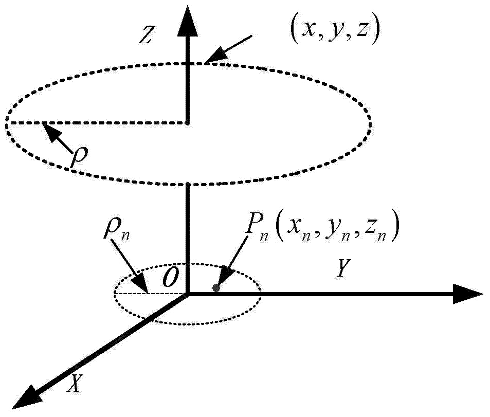
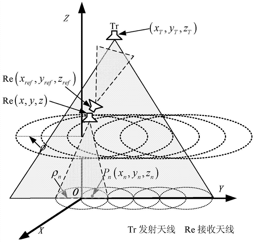
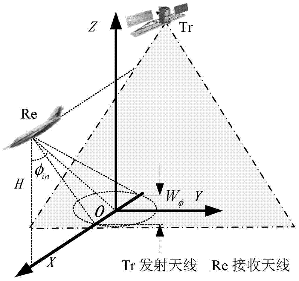
[0017] like figure 1 As shown, the present invention provides a sliding dual-station circumferential synthetic aperture radar imaging method, which is the same as conventional circumferential synthetic aperture radar imaging (such as figure 1 Sliding Bi-static CSAR (S-BiCSAR for short) transmits signals through a stationary or slow-moving platform carrying a radar transmitter subsystem at high altitude, and the airborne platform carries The receiver subsystem "slides" forward, e.g. figure 2 As shown in the figure, it can realize not only the acquisition of non-backscattering characteristics, but also the omnidirectional observation of the observation area, and the acquisition of large-area high-resolution images at the same time.

[0018...


PUM


Abstract

The invention provides a sliding type bistatic circumferential synthetic aperture radar imaging method. The method includes the steps of 1, calculating the 3dB beamwidth of tilt and track of a radar receiving antenna, the pulse repetition frequency of transmitting signals of a radar transmitting antenna and the central sliding spacing of circular motion of a platform where a scene echo signal receiving antenna is arranged during the sliding type bistatic circumferential synthetic aperture radar imaging; 2, outputting attitude parameters of the scene echo signal receiving antenna and a direct wave signal receiving antenna and platform location information according to attitude parameters output by an inertial navigation measurement system of the platform where the scene echo signal receiving antenna is arranged or an inertial navigation measurement system of the radar, and controlling the scene echo signal receiving antenna to receive echo signals of the observation scene; 3, obtaining two-dimensional or three-dimensional images of the observation scene through coherent superposition processing according to sliding type bistatic circumferential synthetic aperture radar imaging echo data and direct wave data acquired in step 2.

Description

technical field [0001] The invention relates to the field of earth observation with microwave imaging technology, and is a sliding dual-station circular synthetic aperture radar imaging method. Background technique [0002] In the mid-to-late 1990s, Falconer et al. first proposed the Circular Synthetic Aperture Radar (CSAR) three-dimensional imaging method (see Falconer D G, Moussally G J. Tomographic imaging of radar sata gathered on a circular flight path about a three-dimensional target zone. Proceedings of SPIE1995, Apr., 1995.), mainly through 360° circular motion of the radar sensor with the platform, and the beam always pointing to the same scene area for the observation area, to realize the acquisition of three-dimensional imaging data of the observation area; then , Soumekh et al. proposed E-CSAR (Elevation Circular SAR, E-CSAR for short) imaging method (see Soumekh M. Synthetic aperture radar signal processing with matlab algorithms. New York; Wiley. 1999) .), but...

Claims


Application Information

Patent Timeline
Patent Type & Authority Applications(China)
IPC IPC(8): G01S13/90
CPCG01S13/904G01S13/9088G01S13/9058
Inventor 丁赤飚谭维贤王彦平陈龙永林赟梁兴东洪文
Owner INST OF ELECTRONICS CHINESE ACAD OF SCI
Why Eureka
Try Eureka