3D grating bonding process for led display

A display and 3D technology, applied in optics, optical components, lamination devices, etc., can solve problems such as unevenness, high product scrap rate, edge wrinkles of grating film and transparent substrate, and reduce requirements and dependencies Sexuality, easy mass production, and the effect of mass production

Active Publication Date: 2017-03-08
SHENZHEN AOTO ELECTRONICS
View PDF6 Cites 0 Cited by
  • Summary
  • Abstract
  • Description
  • Claims
  • Application Information

AI Technical Summary

Problems solved by technology

[0003] There are some traditional grating laminating equipment such as cold laminator, hot laminator and laminating machine, which can complete some simple laminating actions, but these machines and laminating processes are not perfect enough, and there are many problems. The main problems are as follows: 1) During the bonding process, human eyes are mainly used to judge the bonding position, and manual positioning is used, so that the accuracy and slope of the bonding cannot be guaranteed; 2) The bonding of the grating film and the transparent substrate There are wrinkles on the edge of the joint; 3) It is easy to have a small amount of air bubbles and uneven bonding in the sample after the bonding, so the scrap rate of the product is high; 4) During the bonding process, the operator The requirements and dependencies are relatively high, and it requires the cooperation of multiple people to complete

Method used


Image

  • 3D grating bonding process for led display
  • 3D grating bonding process for led display
  • 3D grating bonding process for led display

Examples


Embodiment 1

[0048] Embodiment one Transparent optical adhesive 3 is selected as OCA double-sided adhesive

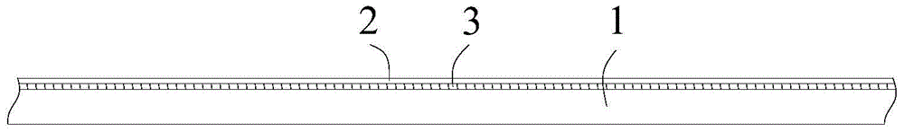
[0049] In this embodiment, the transparent optical adhesive 3 provided in step S1 is selected as the OCA double-sided adhesive, then in step S1, in addition to marking the transparent substrate 1 and the grating film 2 with marking points, the OCA double-sided adhesive should also be marked Identify points.

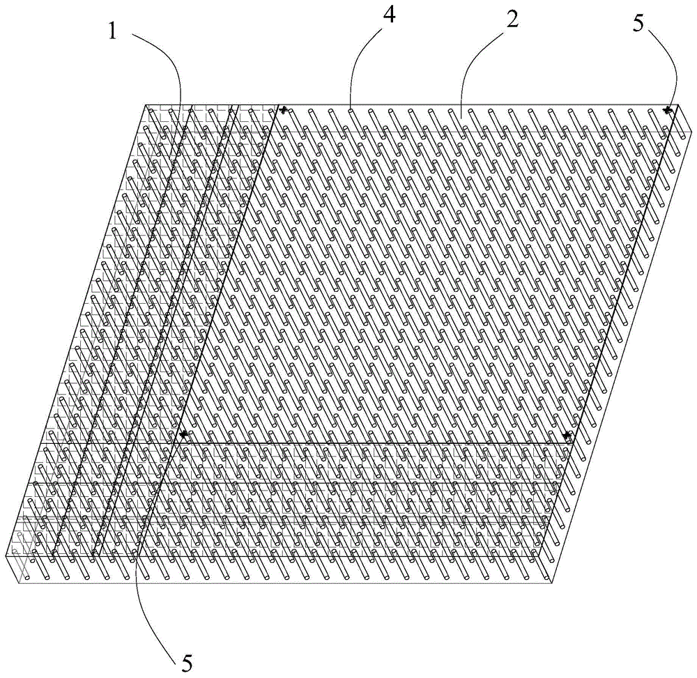
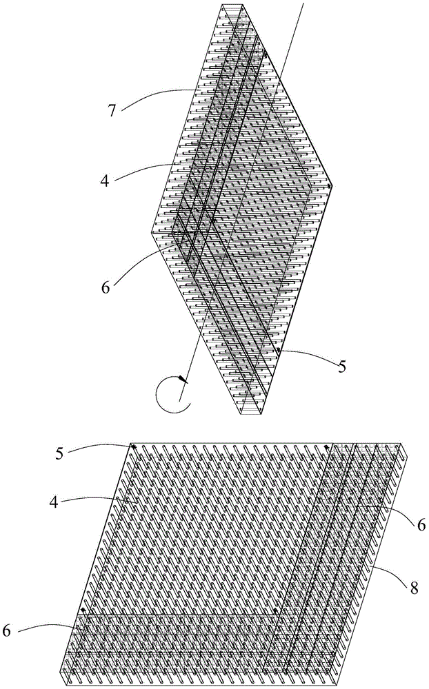
[0050] Further, in this embodiment, the raw materials placed on the first workbench 7 and the raw materials placed on the second workbench 7 in step S2 should first be OCA double-sided adhesive tape and grating film 2 respectively. , that is, the OCA double-sided tape should be laid flat on the first workbench 7 , and the grating film 2 should be laid flat on the second workbench 8 .

[0051] Further, as figure 2 and image 3 As shown, in order to facilitate the OCA double-sided adhesive tape and the grating film 2 to be respectively arranged on the table tops of the fir...

Embodiment 2

[0057] Embodiment two Transparent optical glue 3 is selected as LOCA glue

[0058] The main technical features of this embodiment are generally the same as those of Embodiment 1, and will not be repeated here. The difference between it and Embodiment 1 is:

[0059] 1) In the above step S1, the 3 layers of transparent optical glue are selected as LOCA glue. Because LOCA glue is liquid, it is not necessary to mark it in the above step S1, but to avoid the subsequent lamination process. , because the LOCA glue is doped with air bubbles, resulting in air bubbles in the bonded sample, in this embodiment, the air bubbles inside the LOCA glue should be eliminated in step S1, which is usually carried out in a vacuum environment.

[0060]2) Because the transparent optical glue 3 is selected as LOCA glue, another difference between this embodiment and the first embodiment is that the raw material arranged on the table top of the first workbench 7 in this embodiment is the grating fil...


PUM


Abstract

The invention belongs to the technical field of LED display screens, and aims to provide a 3D (three-dimensional) grating laminating process of an LED display screen. The process includes the steps: providing a transparent substrate and a grating film with identification points, and a transparent optical adhesive; according to different transparent optical adhesives, flatly arranging two kinds of the raw materials on table tops of two working tables respectively, using cameras on the working tables for respectively capturing the identification points of the raw materials, and displaying related information on a display, using application software for calculating the position where the first workbench needs to be turned over and the distance by which the second workbench needs to be translated; performing edge sealing and ensuring that the raw materials flatly placed on the two workbenches are incapable of adhering to each other; performing turnover and lamination; finally, selectively subjecting a 3D grating sample to aftertreatment. Thus, a 3D grating is positioned without depending on human eyes, precision and slope of lamination are ensured, the edges are free of folds, product scrap rate is low, and requirements and dependency on operators are lowered.

Description

technical field [0001] The invention belongs to the technical field of LED display screens, and relates to a grating bonding process, in particular to a 3D grating bonding process of an LED display screen. Background technique [0002] Glasses-free 3D display technology is a technology that obtains independent left and right eye picture signals in the same picture without wearing glasses. Compared with the ordinary 2D picture, the picture displayed by this technology is more realistic in three-dimensional sense, and the picture is no longer limited to the screen picture, which can make people feel as if they are on the scene. No need for people to wear special glasses and cost advantages, the related technologies of naked-eye 3D display have been widely developed and applied in the fields of liquid crystal display, 3D stereoscopic pictures, etc., and are now becoming more and more mature. As a new 3D display field, the light-emitting diode (Light-EmittingDiode, referred to ...

Claims


Application Information

Patent Timeline
Patent Type & Authority Patents(China)
IPC IPC(8): G02B27/22B32B37/12G09F9/33
Inventor 金福报宋呈群张奇刘玲李选中
Owner SHENZHEN AOTO ELECTRONICS
Why Eureka
Try Eureka