
Method and device for detecting CPU over-clock working state

A technology of working status and overfrequency, which is applied in the computer field, can solve the problems of not being able to obtain product working status data conveniently and accurately, reduce CPU warranty costs, etc., and achieve the effect of reducing CPU warranty costs and reducing the occupation of system resources

Active Publication Date: 2014-10-29
LENOVO (BEIJING) CO LTD
View PDF6 Cites 3 Cited by
  • Summary
  • Abstract
  • Description
  • Claims
  • Application Information

AI Technical Summary

Problems solved by technology

[0008] The embodiment of the present application provides a method and device for detecting the working status of CPU overclocking, which solves the problem in the prior art that the products that use overclocking software for CPU overclocking function cannot be obtained conveniently and accurately for the products to work beyond the warranty frequency range. The technical problem of working status data has achieved the technical effect of reducing unnecessary CPU warranty costs without affecting the use of the product by users

Method used


Image

  • Method and device for detecting CPU over-clock working state
  • Method and device for detecting CPU over-clock working state

Examples


Embodiment 1

[0040] In the first embodiment, a method for detecting the overclocking working state of the CPU is provided, which is applied to electronic devices with at least a CPU and a BIOS. In practical applications, it can be applied to computers or electronic products such as smart phones.

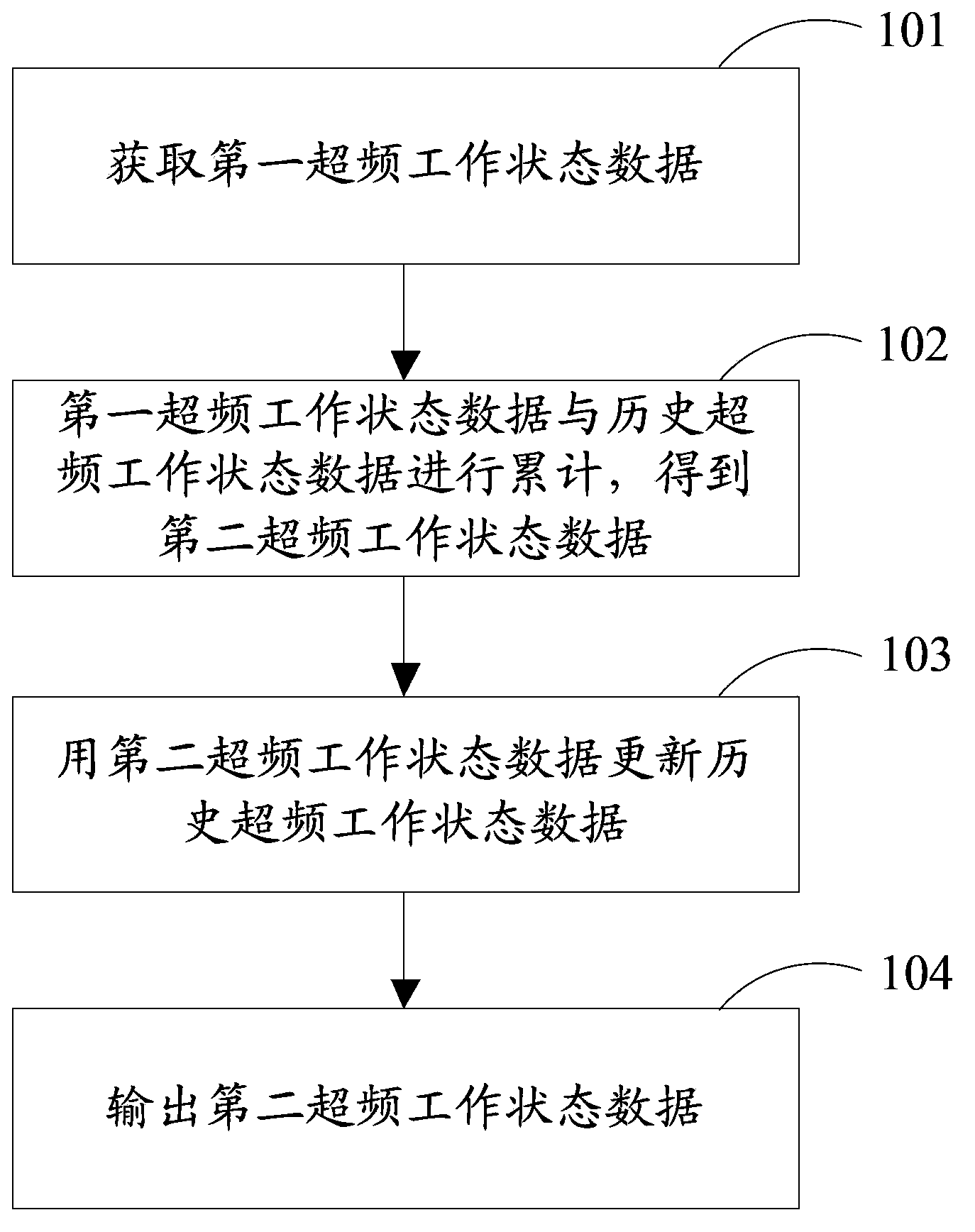
[0041] Please refer tofigure 1 , which is a flowchart of a method for detecting the CPU overclocking working state in Embodiment 1 of the present application, the method specifically includes steps:

[0042] Step 101, at a first moment, acquire first overclocking working state data when the CPU is working at an overfrequency exceeding a preset frequency;

[0043] In the embodiment of the present invention, at the first moment, before obtaining the first overclocking working state data when the CPU is working at an overfrequency exceeding the preset frequency, it further includes:

[0044] Detect whether the CPU is working at a super frequency exceeding the preset frequency, and obtain a first det...

Embodiment 2

[0077] Embodiment 2 provides a device for detecting the overclocking working state of the CPU.

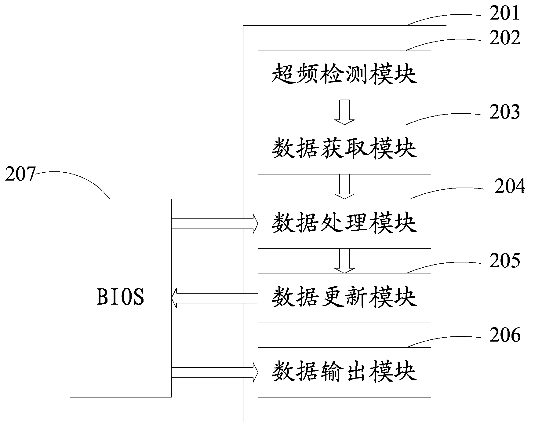
[0078] Please refer to figure 2 , which is a structural diagram of a device for detecting the CPU overclocking working state in Embodiment 2 of the present application, and the device 201 specifically includes:

[0079]The data acquisition module 203 is configured to acquire, at a first moment, first overclocking working state data when the CPU is working at an overfrequency exceeding a preset frequency;

[0080] A data processing module 204, configured to compare the first overclocking working status data with the historical overclocking working status data stored in the BIOS and composed of at least one overclocking working status data of the CPU before the first moment Accumulated to obtain the second overclocking working state data;

[0081] A data update module 205, configured to use the second overclocking working status data to update the historical overclocking working s...


PUM


Abstract

The invention discloses a method and a device for detecting a CPU over-clock working state. The method is used in electronic equipment which is at least provided with a CPU and a BIOS. The method comprises the steps that at a first moment, first over-clock working state data of a CPU with the frequency over preset frequency are obtained; the first over-clock working state data and history over-clock working state data stored in the BIOS are accumulated, and second over-clock working state data are obtained; the second over-clock working state data are used for refreshing the history over-clock working state data; and after triggering information for outputting the second over-clock working state data is received, the second over-clock working state data are output. The method and the device are used for solving the technical problem that in the prior art, a product with over-clock software carrying out a CPU over-clock function is opened, and working state data of working in a range over a quality guaranteeing frequency range of the product cannot be accurately and conveniently obtained.

Description

technical field [0001] The invention relates to the technical field of computers, in particular to a method and a device for detecting the overclocking working state of a CPU. Background technique [0002] When CPU manufacturers produce CPUs, in order to ensure product quality and reliability, they usually leave enough margin for the CPU frequency. At the same time, the main frequency corresponding to the CPU model marked by the manufacturer will not run at full load under normal circumstances. . As far as users are concerned, they are eager to dig out their potential surplus through artificial means, so that the CPU can work stably at a frequency higher than its rated frequency, in exchange for a higher operating frequency, thereby improving performance, that is, overclocking the CPU. Work. At present, many computer and mobile phone manufacturers, in order to meet the user's demand for optimal performance without paying extra money, provide a series of products that open ...

Claims


Application Information

Patent Timeline
IPC IPC(8): G06F11/22
Inventor 罗曦牟宗山
Owner LENOVO (BEIJING) CO LTD
Learn More