
Method for performing test of thermal management system

A thermal management system and a management system technology, applied in the field of testing for the implementation of thermal management systems, can solve problems such as high warranty costs, and achieve the effects of reducing warranty costs, reducing possibilities, and improving quality

Pending Publication Date: 2021-11-05
AUDI AG
View PDF3 Cites 1 Cited by
  • Summary
  • Abstract
  • Description
  • Claims
  • Application Information

AI Technical Summary

Problems solved by technology

This results in high warranty costs for the manufacturer

Method used


Image

  • Method for performing test of thermal management system

Examples


Embodiment Construction

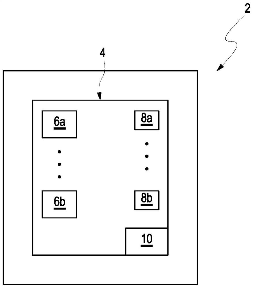
[0038] figure 1 A schematic diagram shows a vehicle 2 , here a motor vehicle or a motor vehicle, in which an embodiment of the thermal management system 4 according to the invention is arranged, that is to say installed and / or constructed.

[0039] The thermal management system 4 comprises a plurality of thermal components 6a, 6b, designed for example as pumps, valves, heaters or lines. Furthermore, the thermal management system 4 comprises a plurality of sensors 8 a , 8 b , which are designed, for example, as temperature sensors or thermometers, pressure sensors and electrical sensors 8 a , 8 b , for example current and voltage meters. Furthermore, thermal management system 4 includes a monitoring device 10 in the embodiment described here, which is designed to monitor and thus control and / or regulate the operation of thermal management system 4 in vehicle 2 .

[0040] Furthermore, the monitoring device 10 of the thermal management system 4 is designed to carry out a self-te...


PUM


Abstract

The invention relates to a method for performing a test of a thermal management system (4) for a vehicle (2). The thermal management system (4) includes a number of thermal components (6a, 6b) and at least one sensor (8a, 8b), wherein a setup of the thermal management system (4) is tested by a control device (10) before delivery of the vehicle when the thermal management system (4) is or will be incorporated in the vehicle (4) during a final assembly.

Description

technical field [0001] The invention relates to a method for performing a test of a thermal management system and a thermal management system. Background technique [0002] The increasing functional complexity of thermal management systems requires a relatively complex construction (structure and installation arrangement) of such thermal management systems, which have to undertake various functions, such as heating and cooling of batteries and heat pump functions . [0003] Due to the large number of hoses, valves and coupling points, even with error-proofing and quality assurance when assembling thermal management systems, incorrect assembly occurs again and again. These include, in particular, incorrect arrangements or incorrect connections of hoses and sensors on components of the thermal management system. Due to these faulty configurations at least some functions of the thermal management system may not be available, so that the thermal management system cannot be del...

Claims


Application Information

Patent Timeline
Patent Type & Authority Applications(China)
IPC IPC(8): G01M99/00G01M17/007B60H1/00H01M10/613H01M10/615H01M10/625H01M10/635
CPCG01M99/00G01M99/005G01M17/007B60H1/00642H01M10/613H01M10/615H01M10/625H01M10/635Y02T10/70Y02E60/10B60L58/27B60L58/26B60L1/02B60L2240/545H01M10/486H01M2220/20B60L58/24
Inventor M·伦茨
Owner AUDI AG
Learn More