
Time domain identification method of random dynamic loads

A random dynamic, time domain identification technology, applied in special data processing applications, instruments, electrical digital data processing, etc., can solve the problem of load identification results deviation, inability to consider the randomness of external loads, etc., to achieve intuitive methods and computational efficiency. high effect

Inactive Publication Date: 2014-10-29
SOUTHEAST UNIV
View PDF2 Cites 28 Cited by
  • Summary
  • Abstract
  • Description
  • Claims
  • Application Information

AI Technical Summary

Problems solved by technology

Although this type of method can accurately obtain the external load information on the structure based on the single-measured dynamic response data, the randomness of the external load cannot be considered by only relying on the single-measured response data to identify the dynamic load.
In fact, many external excitations, such as the excitation of the road surface or rails to the wheels, the excitation of earthquake / wind loads, the excitation of ocean waves to the offshore platform, and the excitation of aerodynamic loads on the aircraft, etc., present a certain "randomness" in themselves. structure, the dynamic response will also present "randomness"; therefore, a single measured structural dynamic response can only be one sample of the structural random dynamic response information, which is obtained by using a deterministic dynamic load identification method based on a certain response sample The dynamic load information can only partially reflect the random dynamic load excitation; in addition, the dynamic response error contained in a single measurement is also used as a part of the "true response" in the deterministic dynamic load identification, causing deviations in the load identification results

Method used


Image

  • Time domain identification method of random dynamic loads
  • Time domain identification method of random dynamic loads
  • Time domain identification method of random dynamic loads

Examples


Embodiment

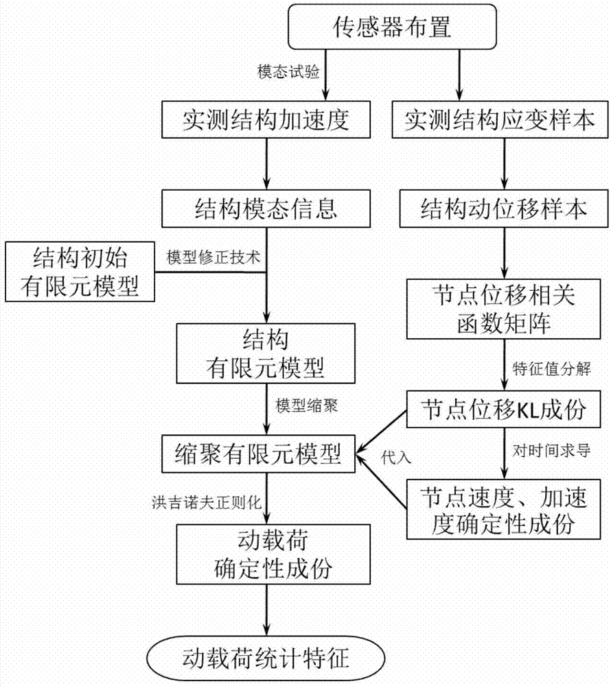
[0028] Embodiment: the random dynamic load identification method of the present invention comprises the following steps:

[0029] (1) Arrange strain and acceleration sensors on the engineering structure, and measure the dynamic strain and acceleration response samples of the structure;

[0030] (2) Establish a structural finite element model for the engineering structure, and then carry out model condensation to obtain the structural finite element model after condensation and the position matrix Q of the load after condensation that matches the corresponding degrees of freedom of the measured dynamic strain response signal c , the finite element model of the structure after polycondensation includes the mass matrix M after polycondensation c , the damping matrix C after polycondensation c and the stiffness matrix K after polycondensation c ;

[0031] First, the initial finite element model of the engineering structure is established; for the engineering structure, the dyna...


PUM


Abstract

The invention discloses a time domain identification method of random dynamic loads. The time domain identification method is characterized by comprising the following steps that (1) a strain sensor and an acceleration sensor are arranged on an engineering structure, and dynamic strain samples and acceleration response samples of the structure are obtained through measurement; (2) an accurate structure finite element model is established for the engineering structure, model condensation is conducted, and a condensed finite element model matched with the freedom degree of a dynamic strain response signal obtained through actual measurement is obtained; (3) on the basis of a dynamic strain sample set obtained through actual measurement, the deterministic component of structure random dynamic response is obtained through the KL decomposition technology; (4) deterministic components of the random dynamic loads are identified by the adoption of the direct inversion method and the Tikhonov regularization method; (5) the statistic characteristics, namely, the average time history and the variance, of the random dynamic loads are obtained.

Description

technical field [0001] The invention belongs to the technical field of random dynamic load identification, and relates to a time-domain random dynamic load identification method based on KL decomposition technology. Background technique [0002] There are mainly two methods to obtain the dynamic load acting on the structure: direct measurement method and indirect identification method. The direct measurement method can obtain the external load information conveniently and accurately for the working condition of discrete external excitation and the sensor is conveniently arranged at the action position. However, in many working conditions, it is difficult or even impossible to obtain some important dynamic load information through the direct measurement method. For example, the wheel-rail contact load of the moving carriage, the aerodynamic load borne by the aircraft during flight, and the dynamic load of the offshore platform structure subjected to strong winds or waves, etc...

Claims


Application Information

Patent Timeline
Patent Type & Authority Applications(China)
IPC IPC(8): G06F19/00
Inventor 吴邵庆费庆国韩晓林
Owner SOUTHEAST UNIV
Learn More