Automatic digitalized level control method

A technology of automatic level and control method, applied in the field of signal sources, can solve the problems of large debugging workload, cumbersome process, long loop stabilization time, etc., to reduce design cost and complexity, improve work efficiency, and fast stabilization speed. Effect

Active Publication Date: 2014-10-29
CHINA ELECTRONIS TECH INSTR CO LTD
View PDF4 Cites 8 Cited by
  • Summary
  • Abstract
  • Description
  • Claims
  • Application Information

AI Technical Summary

Problems solved by technology

[0005] Using the traditional analog automatic level control method, the circuit is more complicated, the debugging workload is heavy, and the loop stabilization time is longer, mainly manifested in:
[0006] 1) The traditional analog automatic level control method needs to add logarithmic amplification and compensation circuits in order to make the detection level correspond to the reference level in proportion. Analog circuits are also used in the comparison and integration with the reference level. The entire system hardware The circuit is more complicated, the cost is higher, and the technical requirements for the hardware circuit are higher;
[0007] 2) In order to realize the normal operation of the logarithmic amplifier circuit in the entire analog power range, the traditional analog automatic level control method needs to increase the logarithmic inflection point and detection offset compensation, so as to facilitate the adjustment of the linearity at both ends of the range, that is, when the large signal and small signal are input. Therefore, manual debugging is required for the differences of each machine, and the process is cumbersome, which affects the efficiency of system debugging;
[0008] 3) The traditional analog automatic level control method uses the comparison result of the reference level to adjust the linear modulation voltage of the signal path through the analog integration link. According to the difference of the integration bandwidth, the response speed of the control voltage is different, generally at the μs level, which affects the Steady speed at final power

Method used


Image

  • Automatic digitalized level control method
  • Automatic digitalized level control method
  • Automatic digitalized level control method

Examples


Embodiment Construction

[0028] Below in conjunction with accompanying drawing and specific embodiment the present invention is described in further detail:
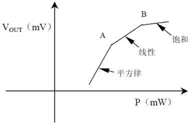
[0029] The basic idea of ​​the present invention is: by analyzing the characteristics of the output signal of the analog power monitoring circuit, a digital automatic level control method is proposed. The digital processing can effectively reduce the cost and technical complexity of the automatic level control circuit, and is beneficial to improve the work efficiency of system debugging.

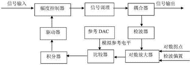
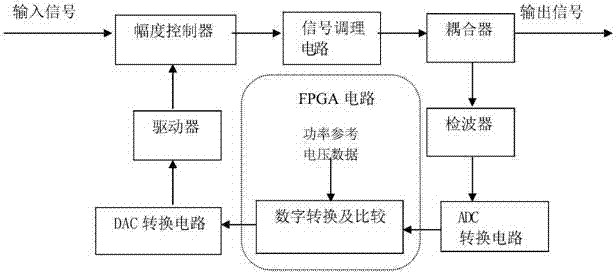
[0030] Specifically, combine image 3 As shown, the signal source output circuit includes an amplitude controller, a signal conditioning circuit, a coupler and a digital automatic level control circuit.

[0031] The digital automatic level control circuit includes a wave detector, an ADC conversion circuit, an FPGA circuit, a DAC conversion circuit and a driver. The input signal passes through the amplitude controller, the signal conditioning circuit and the...


PUM


Abstract

The invention belongs to the field of signal sources and particularly discloses an automatic digitalized level control method. The automatic digitalized level control method includes the following steps that a signal generated by a signal source output circuit enters a detector and a detection voltage is generated; the detection voltage enters an analog to digital converting (ADC) circuit to be subjected to ADC sampling processing to form a digital signal which is sent to a field programmable gate array (FPGA) circuit, the digital signal is amplified and subjected to logarithm operation in the FPGA circuit to obtain voltage data which form a linear relation with power reference voltage data that are stored in the FPGA circuit, and then the voltage data are directly compared with the power reference voltage data; a compared result is subjected to proportional conversion to enter a digital to analog converting (DAC) circuit to be converted into an analog control voltage; the analog control voltage is fed back to the signal source output circuit by a driver, and power fixed amplitude control over the signal source output circuit can be achieved. According to the automatic digitalized level control method, accurate output control over a general signal source within a certain power range can be achieved by a simple hardware circuit design.

Description

technical field [0001] The invention belongs to the field of signal sources, and in particular relates to a digital automatic level control method. Background technique [0002] In the field of general signal sources, the amplitude of the output signal is generally required to meet a certain degree of accuracy. In order to achieve precise control of the output power, automatic level control technology is used to ensure the accuracy of the output power. Automatic level control technology is a common method for automatic and precise control of signal amplitude, which directly affects the power characteristics of the output signal of the signal source, such as accuracy and stability. In the field of general signal sources, the traditional analog automatic level control loop is generally composed of a power monitoring circuit, a power comparison circuit and a control voltage forming circuit. The loop block diagram is as follows: figure 1 shown. [0003] Depend on figure 1 It ...

Claims


Application Information

Patent Timeline
Patent Type & Authority Applications(China)
IPC IPC(8): H03K19/0175
Inventor 齐彦君宫夏刘娜牛大胜
Owner CHINA ELECTRONIS TECH INSTR CO LTD
Why Eureka
Try Eureka