Transmission method for uplink control information and user equipment

A technology for user equipment and control information, which is applied in the field of communication and can solve the problems of high DM-RS overhead and low system throughput

Inactive Publication Date: 2014-10-29
HUAWEI TECH CO LTD
View PDF4 Cites 20 Cited by
  • Summary
  • Abstract
  • Description
  • Claims
  • Application Information

AI Technical Summary

Problems solved by technology

[0007] The present invention provides a method for transmitting uplink control information and user equipment, which are used to solve the problem in the prior art that because each time slot has a DM-RS, the overhead of the uplink DM-RS is large and the system throughput low technical issues

Method used


Image

  • Transmission method for uplink control information and user equipment
  • Transmission method for uplink control information and user equipment
  • Transmission method for uplink control information and user equipment

Examples


Embodiment 1

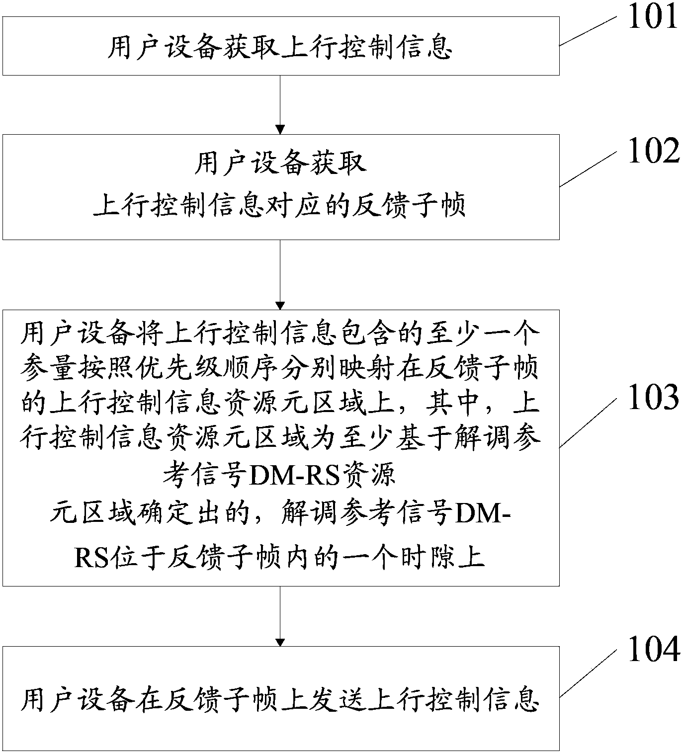
[0131] This embodiment provides a method for transmitting uplink control information, which is used to transmit uplink control information through PUSCH. Please refer to Figure 2a As shown, it is a flow chart of the transmission method, and the method includes:

[0132] Step 101: the user equipment acquires uplink control information;

[0133] Step 102: the user equipment obtains the feedback subframe corresponding to the uplink control information;

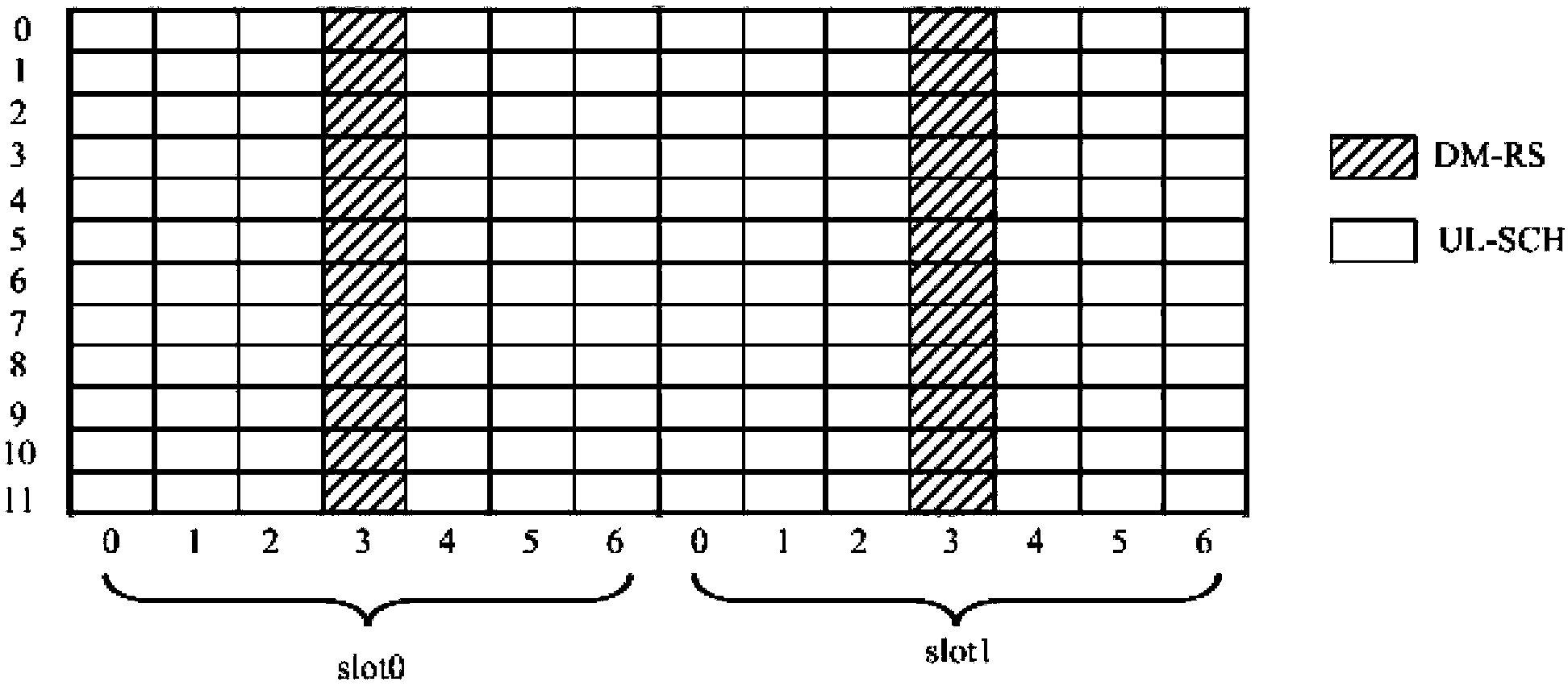
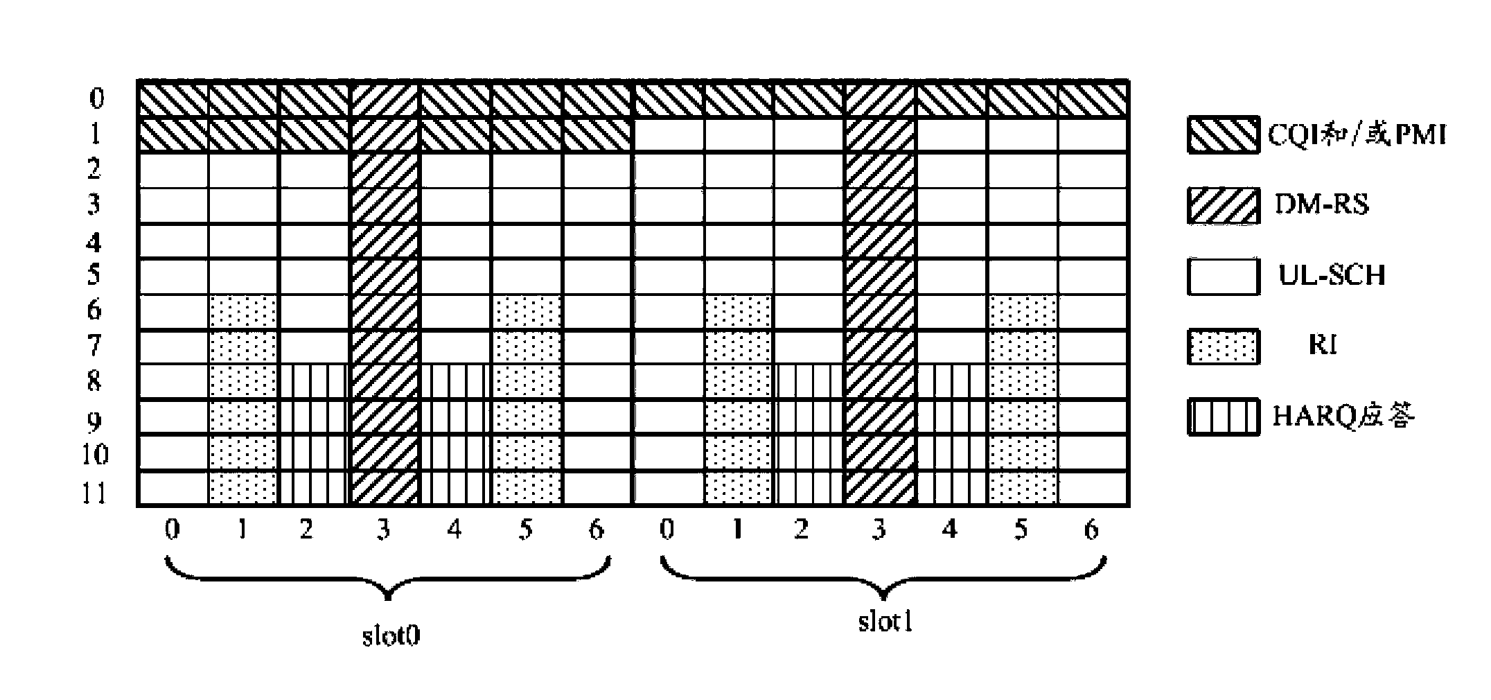
[0134] Step 103: The user equipment maps at least one parameter included in the uplink control information to the uplink control information resource element area of ​​the feedback subframe in order of priority, wherein the uplink control information resource element area is at least based on the demodulation reference signal DM- Determined by the RS resource element area, the demodulation reference signal DM-RS is located on a time slot in the feedback subframe;

[0135] Step 104: the user equipment sends uplink control infor...

Embodiment 2

[0262] This embodiment also provides a user equipment, please refer to Figure 11 As shown, the electronic equipment includes:

[0263] The first obtaining unit 201 is configured to obtain uplink control information and send the uplink control information to the second obtaining unit 202; the second obtaining unit 202 is configured to receive uplink control information from the first obtaining unit 201 and obtain the uplink control information The corresponding feedback subframe; the mapping unit 203 is configured to map at least one parameter contained in the uplink control information on the uplink control information resource element area of ​​the feedback subframe in order of priority; wherein, the uplink control information resource element area is at least Determined based on the demodulation reference signal DM-RS resource element area, the demodulation reference signal DM-RS is located on a time slot in the feedback subframe; the sending unit 204 is configured to recei...

Embodiment 3

[0298] This embodiment provides a user equipment, please refer to Figure 12 As shown in , it is a conceptual diagram of a hardware implementation example of a user equipment, and the user equipment includes:

[0299] The processor 301 is configured to acquire uplink control information, and acquire a feedback subframe corresponding to the uplink control information; and map at least one parameter included in the uplink control information to the uplink control information resource element area of ​​the feedback subframe respectively in order of priority, Wherein, the uplink control information resource element area is determined at least based on the demodulation reference signal DM-RS resource element area, and the demodulation reference signal DM-RS is located on a time slot in the feedback subframe; The uplink control information is sent through the PUSCH on the feedback subframe.

[0300] Among them, in Figure 12 In, bus architecture (represented by bus 300), bus 300 m...


PUM


Abstract

The invention provides a transmission method for uplink control information and user equipment. The method is used for transmitting uplink control information through a PUSCH (Physical Uplink Shared Channel). The method comprises the following steps: the user equipment acquires the uplink control information; the user equipment acquires a feedback sub-frame corresponding to the uplink control information; the user equipment maps at least one parameter included in the uplink control information onto an uplink control information resource meta-area of the feedback sub-frame respectively according a priority sequence, wherein the uplink control information resource meta-area is determined at least based on a demodulation reference signal (DM-RS) resource meta-area, and the demodulation reference signal (DM-RS) is positioned on a time slot in the feedback subframe; the user equipment transmits the uplink control information on the feedback sub-frame.

Description

technical field [0001] The present invention relates to the field of communication technologies, in particular to a method for transmitting uplink control information and user equipment. Background technique [0002] In the long term evolution system (Long Term Evolution; LTE), in order to realize the effective control and scheduling of the base station on different user equipment (UE) transmissions, the UE needs to feed back some information to the base station through the uplink channel, which is the uplink control information ( Uplink Control Information; UCI), uplink control information UCI includes channel quality indicator (Channel Quality Indicator; CQI), precoding matrix indicator (Precoding matrix indicator; PMI), rank indicator (Rank Indication; RI), hybrid automatic repeat request ( One or any combination of Hybrid Automatic Repeat-request; HARQ) responses. Wherein, the HARQ response includes an acknowledgment (Acknowledgment; ACK) and a negative acknowledgment (...

Claims


Application Information

Patent Timeline
IPC IPC(8): H04L1/00H04L1/18
CPCH04L1/1861H04L1/1671H04L1/1854H04L5/0051H04L5/0053
Inventor 黎超
Owner HUAWEI TECH CO LTD
Why Eureka
Try Eureka