The fixed frame for the magnetic pole assembly production line

A fixed frame and production line technology, applied in the field of fixed frame, can solve the problems of increased processing cost, difficult manual assembly, and high noise, and achieve the effects of low recycling cost, easier recycling work, and noise elimination

Active Publication Date: 2016-11-09
南通海隆磁业有限公司
View PDF6 Cites 0 Cited by
  • Summary
  • Abstract
  • Description
  • Claims
  • Application Information

AI Technical Summary

Problems solved by technology

[0002] Patent document PCT / CN2014 / 081921 discloses a magnetic energy turntable, which is equipped with numerous magnetic pole group arrays, each magnetic pole group is composed of 16 pieces of permanent magnets arranged alternately with adjacent magnetic poles, and each magnetic pole group is artificially Due to the small size and thin thickness of each permanent magnet, manual assembly is difficult, inefficient, and error-prone, resulting in multiple permanent magnets attracting each other
In order to improve efficiency and eliminate time loss caused by errors, the factory adopts an automated assembly line to assemble the magnetic pole groups. However, in the production process, the conveying track often vibrates severely and the noise is large. After investigation, the cause of this phenomenon is the rotating shaft. Shaking during the rotation, the reason for the shaking of the shaft is that the coaxiality difference between the upper and lower through holes of the fixed frame, the shaft is forcibly assembled
The fixed frame currently used is made of non-magnetic stainless steel through punching and blanking, and then bent. Since these two steps are carried out separately, the coaxiality of the upper and lower through holes of the bent fixed frame will inevitably be affected. , without changing the process, improving the coaxiality of the upper and lower through holes requires sheet metal processing equipment with a relatively high manufacturing accuracy, which will inevitably lead to an increase in processing costs

Method used


Image

  • The fixed frame for the magnetic pole assembly production line
  • The fixed frame for the magnetic pole assembly production line
  • The fixed frame for the magnetic pole assembly production line

Examples


Embodiment Construction

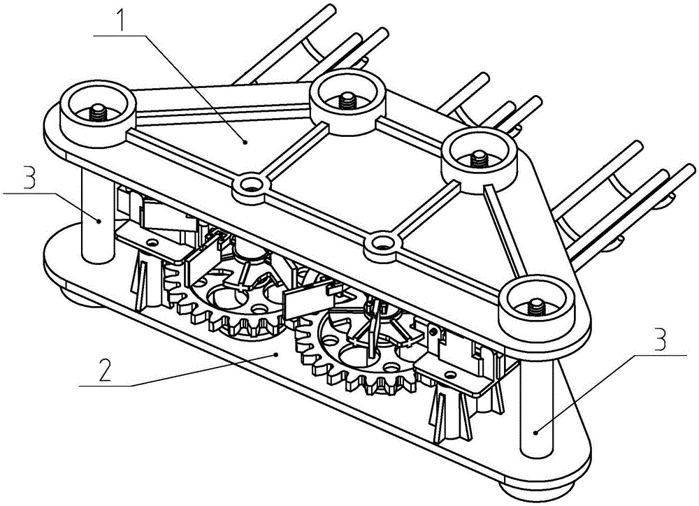
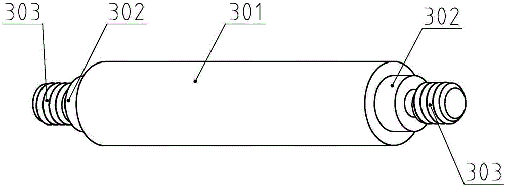
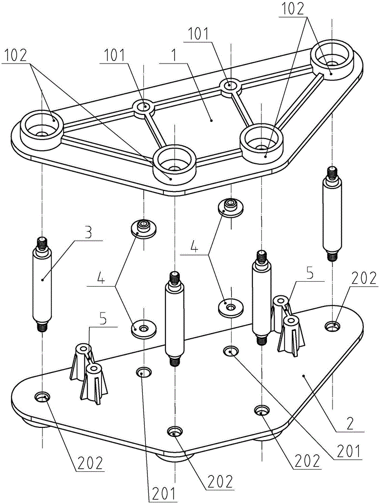
[0023] Such as figure 1 As shown, the fixed frame of the present invention is installed on the assembly line, the second annular boss 102 provided by the fixed seat 2 acts as a support point of the fixed frame, and the second annular boss 102 provided by the fixed cover 1 connects the nut (not shown) Out) or the threaded part 303 of the column 3 is surrounded, which can avoid scratches when workers approach, and improve the safety of production. After the rotating shaft is inserted into the shaft sleeve 4 on the fixed cover 1 and the fixed seat 2, the rotating shaft can rotate freely, that is, the first through hole 201 of the fixed cover 1 and the fixed seat 2 has a relatively high coaxiality, and then Use nuts (not shown) to lock the column 3 and the fixed cover 1, with the help of the ribs provided between the first annular boss 101 and the second annular boss 102, the entire fixing frame can be firm and stable, avoiding shaking The occurrence of the phenomenon.

[0024] ...


PUM


Abstract

Design method for mounting bracket Abstract The invention relates to a design method for a mounting bracket for an assembly line for the magnet group. The method comprises arranging the mounting seat to have an isosceles-trapezoid-like shape, providing a second through hole matching the gap of the pillar at 5 each of four vertexs to the mounting seat, arranging the first through hole symmetrically near the long edge, arranging an interference fit between the first through hole and the sleeve, adjusting the coaxiality of the mounting cover and the first through hole by the gap between the second through hole and the pillar, arranging the first 10 and second shaft portion and the thread portion to be coaxial. Because the whole mounting bracket is fastened after the assurance of coaxiality of the through hole of the mounting seat and the mounting cover is made, so the rotating shaft do not shake during its rotating, the noise is reduced or eliminated. 202 202 201 Fig.3 , / ' )

Description

technical field [0001] The invention relates to the field of automatic assembly lines, in particular to a fixing frame for a magnetic pole group assembly production line. Background technique [0002] Patent document PCT / CN2014 / 081921 discloses a magnetic energy turntable, which is equipped with numerous magnetic pole group arrays, each magnetic pole group is composed of 16 pieces of permanent magnets arranged alternately with adjacent magnetic poles, and each magnetic pole group is artificially Due to the small size and thin thickness of each permanent magnet, manual assembly is difficult, inefficient, and error-prone, resulting in multiple permanent magnets attracting each other. In order to improve efficiency and eliminate time loss caused by errors, the factory adopts an automated assembly line to assemble the magnetic pole groups. However, in the production process, the conveying track often vibrates severely and the noise is large. After investigation, the cause of thi...

Claims


Application Information

Patent Timeline
Patent Type & Authority Patents(China)
IPC IPC(8): B23P19/00
CPCB23P19/00
Inventor 龚柱
Owner 南通海隆磁业有限公司
Why Eureka
Try Eureka