Disc hub assembly and dual mass flywheel

A dual-mass flywheel and disc hub technology, applied in the field of transmission, can solve the problems of large space requirements for the ring gear, complicated manufacturing and assembly of the ring gear, etc., and achieves the effects of easy implementation, low design cost, and easy manufacturing.

Pending Publication Date: 2022-07-29
SCHAEFFLER TECH AG & CO KG
View PDF1 Cites 0 Cited by
  • Summary
  • Abstract
  • Description
  • Claims
  • Application Information

AI Technical Summary

Problems solved by technology

[0004] However, in the above-mentioned noise reduction scheme, the manufacturing and assembly of the gear ring are relatively complicated, and the demand for the ring gear accommodation space is relatively large

Method used


Image

  • Disc hub assembly and dual mass flywheel
  • Disc hub assembly and dual mass flywheel
  • Disc hub assembly and dual mass flywheel

Examples


Embodiment Construction

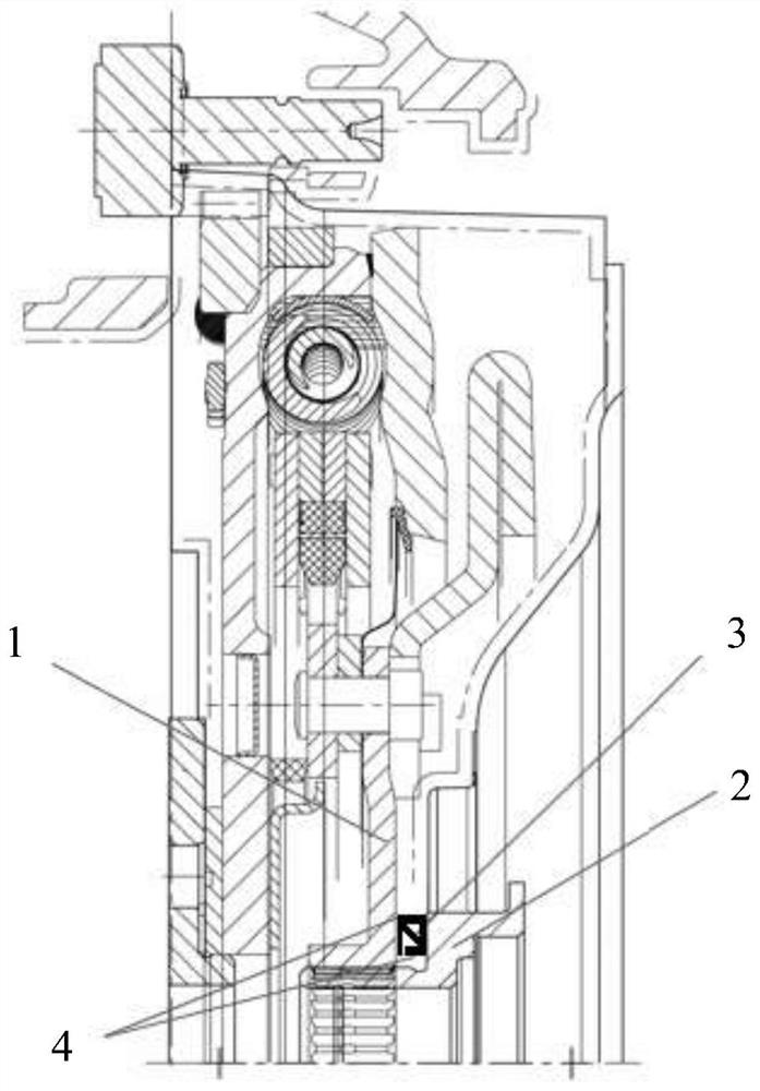
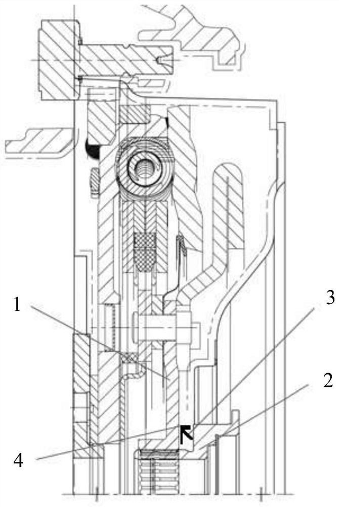
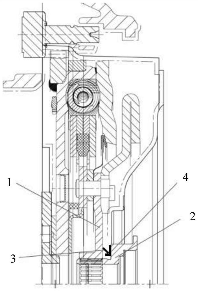
[0032] The following use the Figure 1 to Figure 4 A hub assembly in accordance with four embodiments of the present invention is shown. In various embodiments, the hub assembly may be constructed in a dual mass flywheel for a motor vehicle. The dual mass flywheel is arranged as a vibration damping device between the engine and the transmission of the motor vehicle to isolate torsional vibrations of the engine crankshaft. The transmission input shaft 2 of the transmission can be connected in a rotationally fixed manner to the secondary flywheel 1 . exist Figure 1 to Figure 4 Only one end of the transmission input shaft 2 is partially shown.

[0033] figure 1 A schematic half-sectional view of the disk-hub assembly according to the first embodiment in the state of connection with the transmission input shaft 2 is shown.

[0034] like figure 1 As shown, the hub assembly includes a hub serving as the secondary flywheel 1 of the dual mass flywheel. The secondary flywheel 1...


PUM


Abstract

The invention relates to a disc hub assembly and a dual mass flywheel. The disc hub assembly comprises a disc hub (1) and an elastic component (3), the disc hub (1) is provided with an inner connecting part used for being connected with a shaft piece (2) in an anti-rotation mode on the radial inner side, and the elastic component (3) can be tensioned between the disc hub (1) and the shaft piece (2) in the axial direction when the disc hub (1) is connected with the shaft piece (2) in an anti-rotation mode, so that friction damping in the circumferential direction is formed between the disc hub (1) and the shaft piece (2). The dual-mass flywheel comprises the disc hub assembly.

Description

technical field [0001] The present invention relates to the field of transmission. The present invention particularly relates to a hub assembly. The invention also relates to a dual mass flywheel comprising the above-described disc hub assembly. Background technique [0002] In a motor vehicle provided with an engine, a vibration damping device such as a dual-mass flywheel is often provided between the engine and the transmission to isolate the torsional vibration of the engine crankshaft, which is beneficial to improve the performance of the motor vehicle. In this case, the output disk of the dual-mass flywheel is connected in a rotationally fixed manner to the input shaft of the transmission by means of splines. However, in such a splined coupling there is a gap, especially in the circumferential direction, between the internal splines of the output disc and the external splines of the input shaft. Therefore, when the motor vehicle is idling or in other low-speed drivin...

Claims


Application Information

Patent Timeline
Patent Type & Authority Applications(China)
IPC IPC(8): F16F15/30F16F15/121
CPCF16F15/30F16F15/1215
Inventor 颜克志段启超
Owner SCHAEFFLER TECH AG & CO KG
Why Eureka
Try Eureka