Electro-osmotic drainage consolidation method for electrode pipes

A technology of drainage consolidation and electrode tube, applied in soil protection, infrastructure engineering, construction, etc., can solve the problems of difficulty in guaranteeing the efficiency and effect of electroosmosis, lack of it, and inability to give full play to the advantages of electroosmosis, so as to achieve targeted Strong, improve efficiency, guarantee speed and effect

Active Publication Date: 2014-11-05
武汉谦诚环境技术有限公司
View PDF8 Cites 8 Cited by
  • Summary
  • Abstract
  • Description
  • Claims
  • Application Information

AI Technical Summary

Problems solved by technology

Although the traditional electroosmotic method of electrification sometimes uses two methods of electrode switching and intermittent electrification, the determination of the electrode transition and intermittent electrification time is entirely based on experience; due to the complex characteristics of the soil, the experience of one site is not applicable. Another site, this makes the traditional electroosmosis method lack a clear design method for the power mode, and the efficiency and effect of electroosmosis are difficult to guarantee, so that the advantages of electroosmosis cannot be fully exerted

Method used


Image

  • Electro-osmotic drainage consolidation method for electrode pipes
  • Electro-osmotic drainage consolidation method for electrode pipes
  • Electro-osmotic drainage consolidation method for electrode pipes

Examples


Embodiment 1

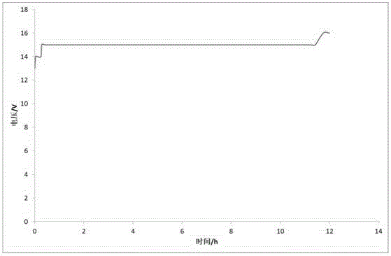
[0039] Such as figure 1 As shown, the drainage area 1 is circular, and the plastic electrode tubes are evenly arranged in squares. The outermost layer 2 electrodes are negatively charged, and the boundary layer 3 is positively charged. The distance between the outermost layer 2 and the boundary layer 3 electrodes is 0.5m. The spacing is 1m, and the power supply adopts the steady flow mode with a current of 300A. All positive electrodes and negative electrodes in the boundary layer 3 are collected and connected to a voltmeter.

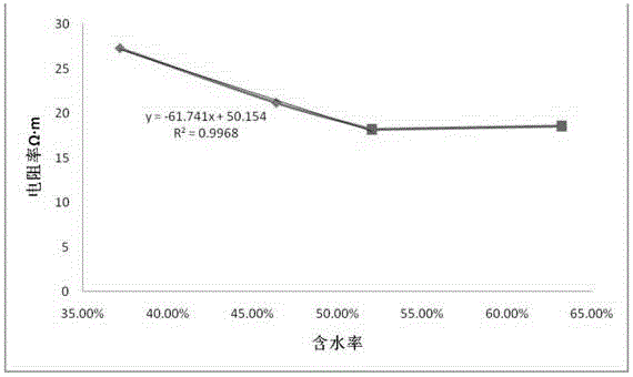
[0040] Use the test device Miller Soil Box to measure the soil resistivity and draw the curve, such as Figure 4 As shown, the moisture content is set to 52%;

[0041] Electrode electrification: Start the vacuum pump to discharge some free water in the soil. After the vacuum is stable, start the DC power supply to electrify the electrode. The electrode electrification method is:

[0042] (1) Reversing power supply at intervals: connect the inner el...

Embodiment 2

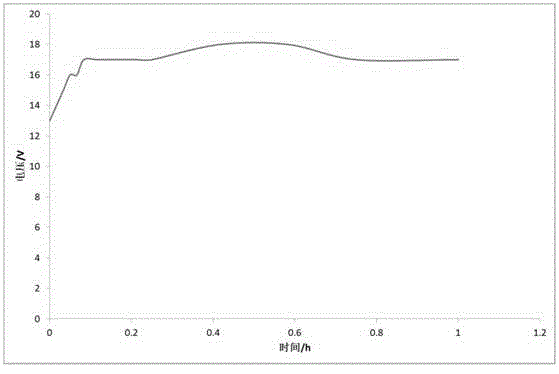
[0048] Such as figure 1 As shown, the drainage area 1 is circular, and the plastic electrode tubes are evenly arranged in squares. The outermost electrode 2 is negatively charged, and the boundary layer 3 is positively charged. The distance between the outermost layer and the boundary layer electrodes is 0.75m. Negative and positive alternating currents are used in sequence, and the electrode spacing in the boundary layer 3 area is 1m. The power supply adopts a regulated power-on mode with a voltage of 80V. All the positive electrodes and negative electrodes in the boundary layer 3 are connected to the ammeter after being collected respectively.

[0049] Use the test device Miller Soil Box to measure the soil resistivity and draw the curve, such as Figure 4 As shown, the moisture content is set to 52%;

[0050] Electrode electrification: Start the vacuum pump to discharge some free water in the soil. After the vacuum is stable, start the DC power supply to electrify the e...


PUM


Abstract

The invention discloses an electro-osmotic drainage consolidation method for electrode pipes. The electro-osmotic drainage consolidation method includes steps of arranging electrodes; arranging pipelines; electrifying the electrodes; stopping electro-osmosis. The step of electrifying the electrodes includes alternately electrifying the electrodes in a direction change manner; continuously electrifying the electrodes; intermittently electrifying the electrodes; repeatedly continuously electrifying the electrodes and intermittently electrifying the electrodes. The electro-osmotic drainage consolidation method has the advantages that a process for connecting currents, voltages and TDR (time domain reflectometry) sensors with one another is adopted, the intensity and the directions of electric fields are timely adjusted according to electric field and soil moisture content space-time distribution conditions fed by circuits, accordingly, electro-osmotic drainage consolidation speeds and effects can be guaranteed, the direction change and intermittent time can be accurately judged as compared with the traditional method for judging the direction change and intermittent time according to experience, and the electro-osmotic drainage consolidation method is high in pertinence for complicated lands.

Description

technical field [0001] The invention relates to the technical field of geotechnical engineering, in particular to a method for electroosmotic drainage consolidation of electrode tubes. Background technique [0002] Soft soil, silt, sludge, tailings and other fine-grained media with high water content and low hydraulic permeability are very difficult to drain and consolidate. The traditional drainage consolidation methods are vacuum preloading and surcharge preloading. However, for fine-grained media with high water content and low hydraulic permeability, the traditional methods are slow, limited in depth, and insufficient in improving the bearing capacity. [0003] For soft soil foundations composed of such media, electroosmosis is a very potential method. It has been more than 200 years since electroosmosis was first discovered. The specific method is to insert a metal electrode in the soil and pass a direct current. Due to the action of the direct current electric field, ...

Claims


Application Information

Patent Timeline
Patent Type & Authority Applications(China)
IPC IPC(8): E02D3/11
CPCE02D3/10E02D3/11
Inventor 庄艳峰陈文王有成杨宏武
Owner 武汉谦诚环境技术有限公司
Why Eureka
Try Eureka