Compressor recirculation valve control to reduce charge air cooler condensate

A charge air cooling, recirculation valve technology for electrical controls, engine controls, machines/engines, etc. to address issues such as increased condensate potential

Active Publication Date: 2014-11-05
FORD GLOBAL TECH LLC
View PDF6 Cites 6 Cited by
  • Summary
  • Abstract
  • Description
  • Claims
  • Application Information

AI Technical Summary

Problems solved by technology

Thus, a closed CRV builds up induction pressure ahead of the throttle, thereby increasing the likelihood of condensate formation in the CAC

Method used


Image

  • Compressor recirculation valve control to reduce charge air cooler condensate
  • Compressor recirculation valve control to reduce charge air cooler condensate
  • Compressor recirculation valve control to reduce charge air cooler condensate

Examples


Embodiment Construction

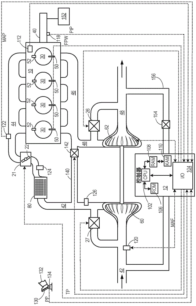
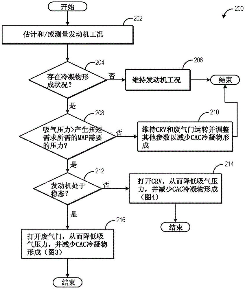
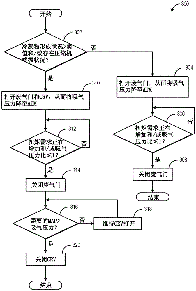
[0012] The following description relates to systems and methods for adjusting a wastegate and / or a compressor recirculation valve in response to condensate formation conditions in a charge air cooler (CAC). engine systems (such as figure 1 The engine system shown) may include a turbocharger where exhaust flow through the turbine drives a compressor. The engine may include a wastegate and a compressor recirculation valve (CRV) operable to divert airflow around the turbine and compressor, respectively. Thus, opening the wastegate and / or CRV, can reduce boost, thereby increasing induction pressure measured upstream of the intake throttle and downstream of the charge air cooler (CAC), and reducing the risk of condensate formation in the CAC possibility. The engine controller may open the wastegate and / or the CRV to reduce the induction pressure during selected driving conditions, such as when the induction pressure is greater than the intake manifold pressure (MAP) required to g...


PUM


Abstract

Methods and systems are provided for adjusting a compressor recirculation valve in response to condensate forming conditions in a charge air cooler (CAC). In one example, a compressor recirculation valve may be opened in response to an induction pressure greater than a threshold pressure when the induction pressure is greater than required to produce a manifold pressure required for a torque demand. Further, a wastegate may be opened to further reduce the induction pressure during certain driving conditions.

Description

technical field [0001] This application relates to compressor recirculation valve control to reduce charge air cooler condensate. Background technique [0002] Engines can use turbochargers or superchargers to compress ambient air entering the engine in order to increase power. The compression of the air can cause an increase in air temperature, so an intercooler or charge air cooler (CAC) can be used to cool the heated air, thereby increasing the air density and further increasing the engine's potential power. Condensation can form in the CAC when the ambient air temperature drops, or during humid or rainy weather conditions, in which case the intake air is cooled below the dew point of the water. Additionally, when the charge air entering the CAC is boosted (eg, suction pressure and boost pressure greater than atmospheric pressure), condensate can form if the CAC temperature drops below the dew point temperature. Condensate can therefore collect at the bottom of the CAC ...

Claims


Application Information

Patent Timeline
Patent Type & Authority Applications(China)
IPC IPC(8): F02B37/16F02M25/07F02D41/00
CPCF02B37/183F02B29/04F02B37/16Y02T10/12
Inventor A·摩热里P·马特瓦斯S·S·雅玛达D·贝尔E·T·安德森J·E·德日斯
Owner FORD GLOBAL TECH LLC
Why Eureka
Try Eureka