
Method for maintaining suction in body cavities

a body cavity and suction technology, applied in the field of gastric tubes, can solve the problems of exposing the lining of the stomach to injury, high suction levels can injure the gastric mucosa, and the lining of the stomach, so as to reduce the pressure within the lumen, prevent excessive negative pressure on the stomach wall, and reduce the negative pressure

Active Publication Date: 2021-05-18
LEIBOFF ARNOLD
View PDF24 Cites 1 Cited by
  • Summary
  • Abstract
  • Description
  • Claims
  • Application Information

AI Technical Summary

Benefits of technology

The invention relates to a device for reducing negative pressure in a gastric tube during surgery. The device includes a pressure relief valve that opens when negative pressure exceeds a certain level, creating a visual signal. This helps to prevent damage to the stomach and allows the surgeon to adjust the suction pressure in real-time. The invention also includes a gastric sleeve that is inserted into the stomach to define the optimal location for resection and closure. Overall, this device improves the safety and effectiveness of gastric surgery procedures.

Problems solved by technology

However, treating personnel, such as nurses or other doctors, may apply higher levels of suction accidently, or purposely if the tube does not seem to be functioning, by dialing up the suction regulator.
High levels of suction can injure the gastric mucosa, the lining of the stomach.
Applying suction through a large caliber tube with multiple apertures may expose the lining of the stomach to injury.
However, this suction controller has disadvantages.
It is relatively bulky and it is situated in line which could interfere with suction when particulate debris or blood clots accumulate in the suction regulator and obstruct flow.

Method used


Image

  • Method for maintaining suction in body cavities
  • Method for maintaining suction in body cavities
  • Method for maintaining suction in body cavities

Examples


Embodiment Construction

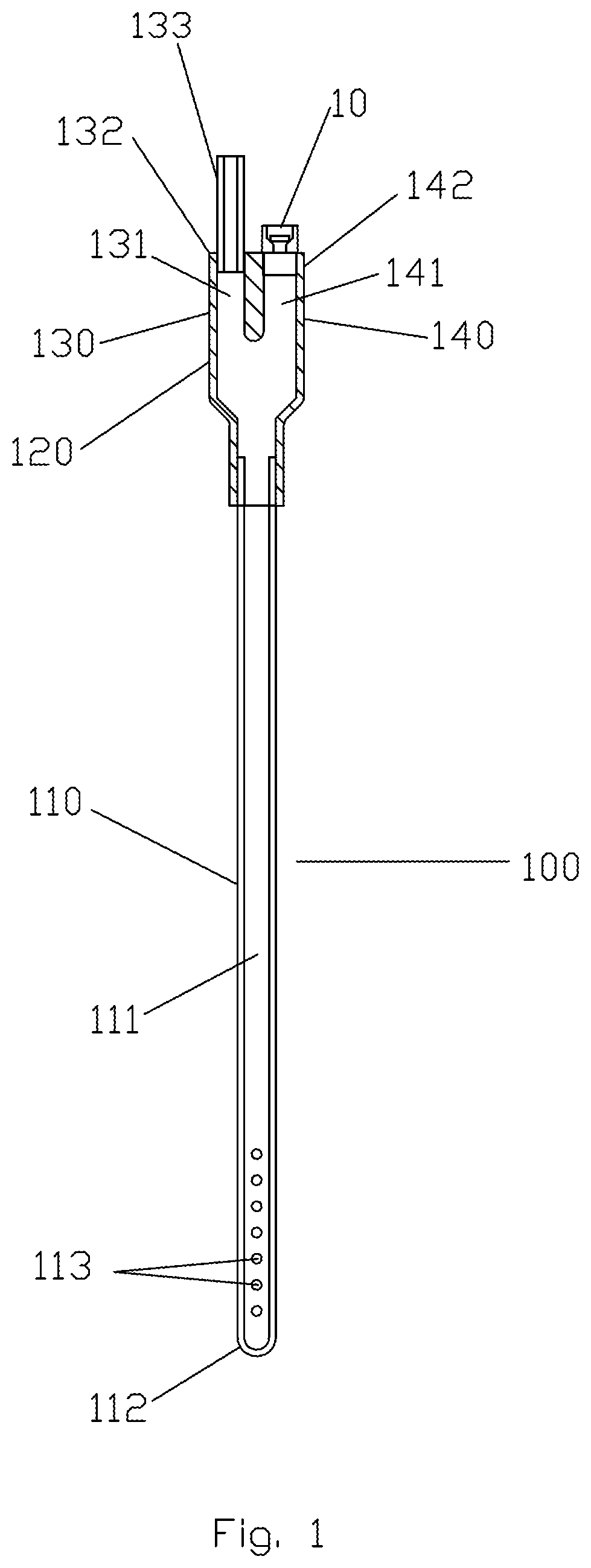
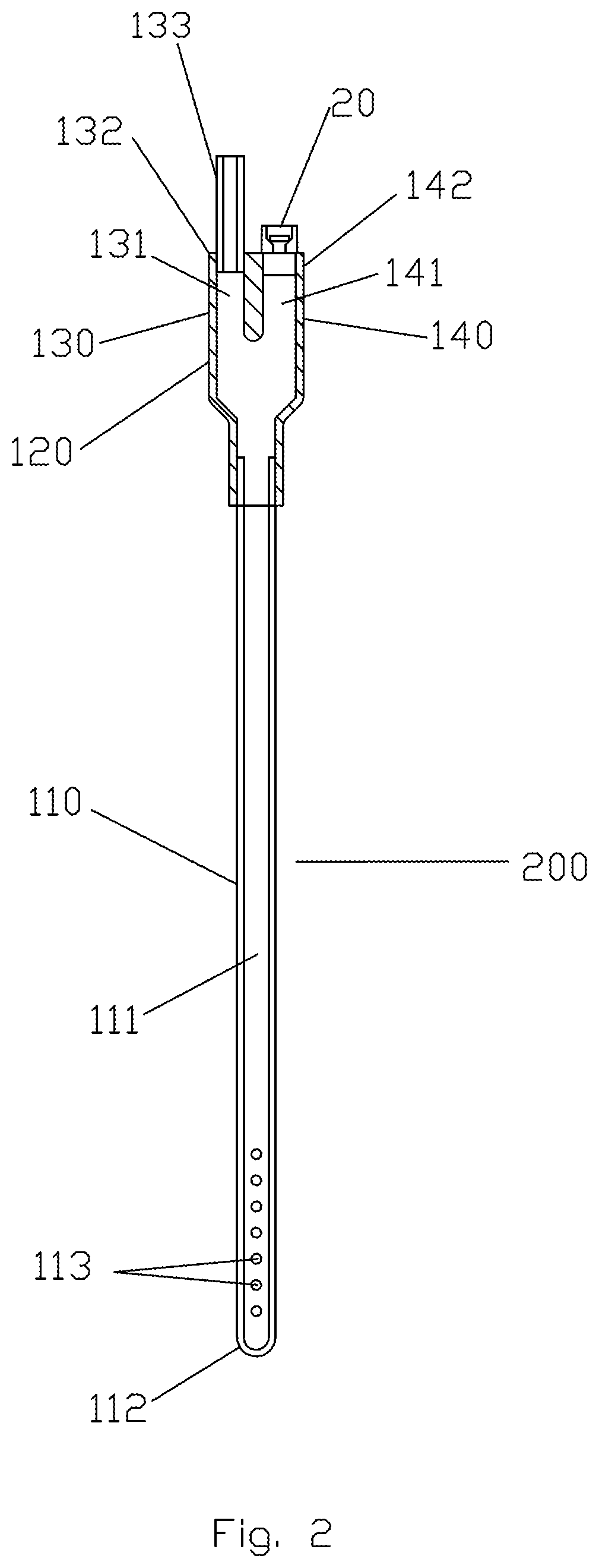
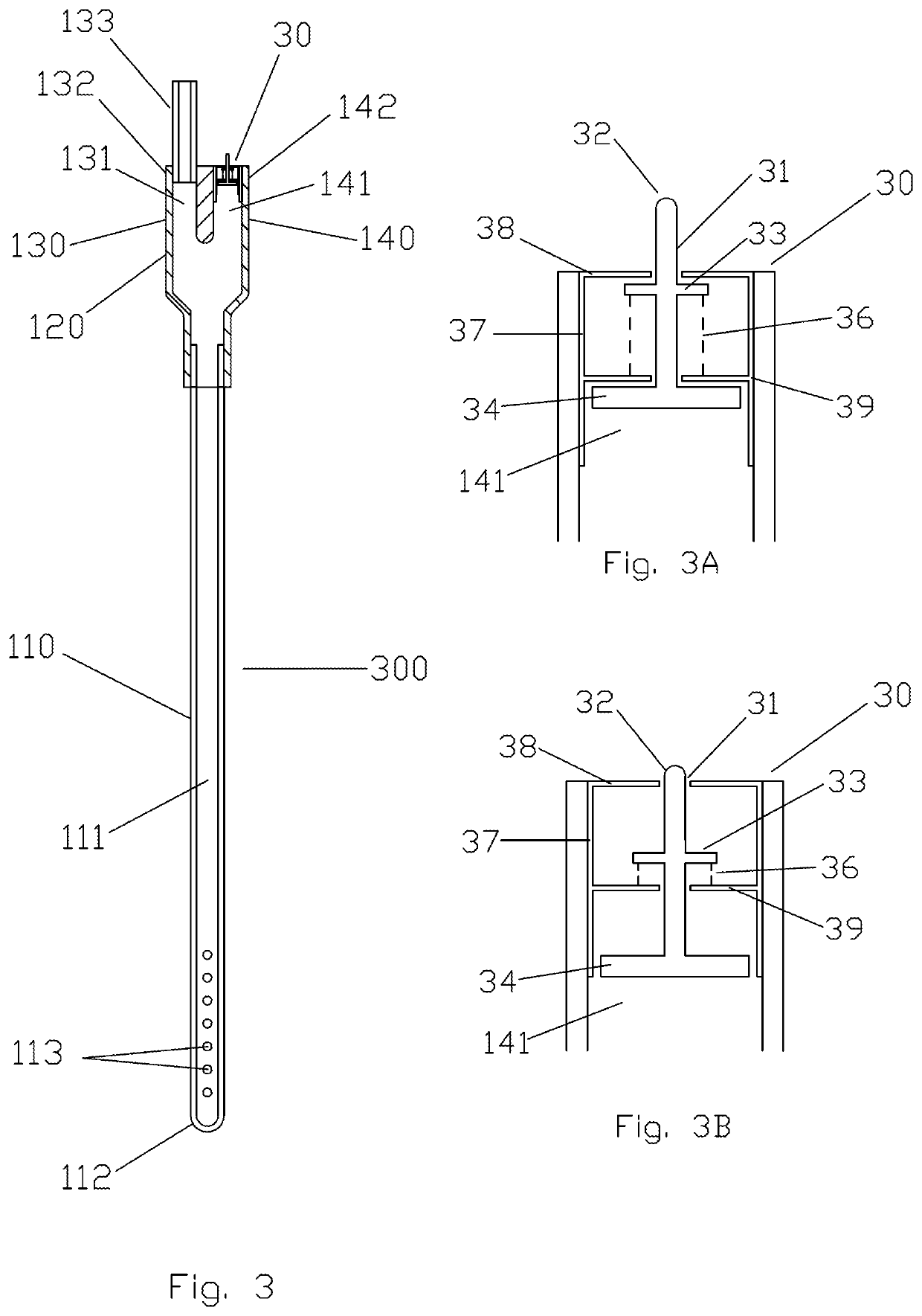
[0038]Referring now to FIG. 1, a first embodiment of a tube for insertion into a body cavity, or more specifically, a gastric tube, according to the invention is designated generally as 100 and includes elongate distal portion 110 and proximal portion 120. Distal portion 110 comprises lumen 111 and at least one aperture 113 in proximity to distal end 112. Proximal portion 120 has two arms, first arm 130 and second arm 140, which may be alongside one another as shown. First arm 130 comprises lumen 131 and proximal end 132. End 132, or extension 133, is adaptable to a tubing from a suction source (not shown). Second arm 140 has lumen 141 and end 142. Lumens 111, 131 and 141 are always in flow communication. Extension 133 is tubular and extends from the end 132, and both the end 132 and the extension 133 may be adaptable to tubing from the suction source. Proximal portion 120 may be formed integral with the distal portion 110 or separate therefrom and then attached securely thereto. Di...


PUM


Abstract

Method for introducing and maintaining a level of negative pressure in a body cavity of at least 80 mmHg using a tube having an elongate distal portion and a proximal portion having first and second arms, each arm having a lumen in flow communication with one another and with the body cavity via apertures at or near the distal end of the tube, wherein the first arm or tubular extension therefrom is adaptable to receive suction from a suction source. An indicator, arranged in relation to the second arm, signals when a specific negative pressure has been exceeded in the tube, or a valve, arranged in relation to the second arm, admits ambient air into the lumen of the second arm when suction is applied to the tube and differential air pressure between the air in the lumens of the tube and ambient air exceeds a specified amount.

Description

FIELD OF THE INVENTION[0001]The present invention relates generally to gastric tubes, including nasogastric tubes and orogastric tubes, and more particularly to methods for maintaining suction in a body cavity using such tubes.BACKGROUND OF THE INVENTION[0002]Gastric tubes, either orogastric or nasogastric, have long been used to aspirate the stomach and to provide a means to introduce materials into the stomach, for example, nutrients, medicines or fluids used for testing, such as contrast for radiological imaging. They are passed through the nose or mouth, through the esophagus and into the stomach. They are particularly useful when the stomach or intestines are not functioning properly, for example during intestinal ileus or obstruction. However, they are often used routinely during certain abdominal surgeries, and at other times that require gastric decompression or feeding.[0003]When gastric tubes are used to aspirate the stomach, negative pressure is delivered to the proximal ...

Claims


Application Information

Patent Timeline
Patent Type & Authority Patents(United States)
IPC IPC(8): A61B17/11A61M1/00A61B17/115A61B17/12A61B17/22A61B17/30A61B5/00
CPCA61B17/1114A61B17/115A61B17/12099A61B17/22A61B5/4255A61B2017/1139A61B2017/22069A61B2017/306A61B2217/005A61M1/008A61J15/0003A61M1/84A61M2210/0618A61M2210/0625A61M2210/1042A61M1/732A61M2205/3344A61M1/742A61M2210/1053A61B2090/063A61F5/0036A61F5/0076
Inventor LEIBOFF, ARNOLD
Owner LEIBOFF ARNOLD
Learn More