Pipe type fuel gas pressure-relief device

A decompression device, gas technology, applied in the direction of the valve device, safety valve, engine components, etc., can solve the problems of unstable flame state, turbulent natural gas flow, complex structure of the pressure reducing valve, etc., to avoid unstable flame state and cost Low, simple structure effect

Inactive Publication Date: 2014-11-05
CHENGDU GUOGUANG ELECTRONICS INSTR
View PDF8 Cites 1 Cited by
  • Summary
  • Abstract
  • Description
  • Claims
  • Application Information

AI Technical Summary

Problems solved by technology

The existing pressure reducing valve has complex structure, high manufacturing cost, and the pressure reducing valve is too large to be installed in a narrow space
[0003] Existing decompression valves, such as a high-pressure natural gas decompression valve disclosed in Chinese Patent Application Publication No. "102052495A", natural gas flows in from the intake end, and enters from the top and bottom direction after passing through the decompression mechanism. When the gas outlet is connected to the cavity, the natural gas will be sprayed onto the cavity wall at this time, causing the natural gas flow entering the gas outlet to be turbulent, which can easily cause flow fluctuations and cause the flame state to be unstable when the user uses it.

Method used


Image

  • Pipe type fuel gas pressure-relief device
  • Pipe type fuel gas pressure-relief device
  • Pipe type fuel gas pressure-relief device

Examples


Embodiment 1

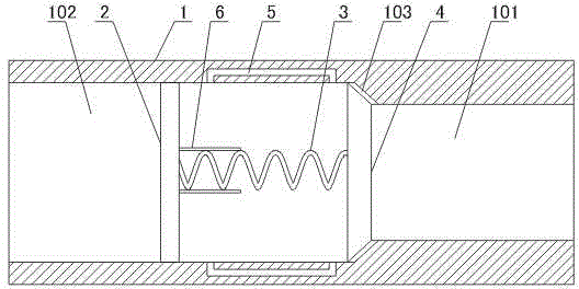
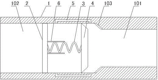
[0033] Such as figure 1 As shown, the tubular gas decompression device includes: a pipe body 1, two ends of the pipe body 1 are provided with connecting threads, and the space in the pipe body 1 is composed of a high-pressure chamber 101 and a low-pressure chamber 102; the inner diameter of the high-pressure chamber 101 is smaller than that of the low-pressure chamber The inner diameter of 102; fixed body 2, fixed body 2 is arranged in low-pressure chamber 102 and is connected with the inner surface of low-pressure chamber 102, and fixed body 2 is provided with the gap that passes through for gas; Spring 3, one end of spring 3 and fixed body 2 Connection; piston 4, piston 4 is connected with the other end of spring 3, spring 3 pushes piston 4 close to the end of high-pressure chamber 101; vent hole 5, vent hole 5 is evenly opened on the tube wall of low-pressure chamber 102, vent hole Both ends of 5 communicate with the inner space of the low-pressure chamber 102 , and the ven...

Embodiment 2

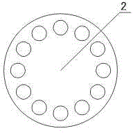
[0037] Such as figure 1 with image 3 As shown, this embodiment further describes the fixed body 2 on the basis of the embodiment 1. The fixed body 2 is a porous plate.

[0038] The holes on the fixed body 2 are used for gas to pass through.

Embodiment 3

[0040] Such as figure 1 with Figure 4 As shown, this embodiment further describes the fixed body 2 on the basis of the embodiment 1. The fixed body 2 includes a circular middle plate 201 and a connecting rod 202 evenly arranged on the outer surface of the circular middle plate 201. The connecting rod 202 is connected to the inner surface of the low-pressure chamber 102, and the spring 3 is connected to the circular middle Board 201 is connected.

[0041] The gaps between the connecting rods 202 are used for gas to pass through.


PUM


Abstract

The invention discloses a pipe type fuel gas pressure-relief device. The device comprises a pipe body, a fixing body, a spring, a piston and ventilating holes, wherein the two ends of the pipe body are provided with connecting threads, the space in the pipe body is composed of a high-pressure cavity and a low-pressure cavity, and the inner diameter of the high-pressure cavity is smaller than that of the low-pressure cavity; the fixing body is arranged in the low-pressure cavity and connected with the inner surface of the low-pressure cavity, and a gap for gas to pass through is formed in the fixing body; one end of the spring is connected with the fixing body; the piston is connected with the other end of the spring, and the piston is pushed by the spring to be tightly attached to the end of the high-pressure cavity; the ventilating holes are evenly formed in the pipe wall of the low-pressure cavity, the two ends of each ventilating hole are both communicated with the internal space of the low-pressure cavity, and the ventilating holes are located between the fixing body and the ends of the high-pressure cavity. The pipe type fuel gas pressure-relief device is simple in structure, small in size and capable of being conveniently connected with a fuel gas conveying pipe. Due to the pipe type fuel gas pressure-relief device, fuel gas flow turbulence can not be caused, and the situation that the flame state is not stable is avoided.

Description

technical field [0001] The invention relates to the field of gas transportation, in particular to a gas decompression device. Background technique [0002] The gas needs to be kept at high pressure during the transportation process, and the gas pressure needs to be reduced when it is used at the user end. Currently, in order to reduce the gas pressure at the user end, a pressure reducing valve is usually provided on the gas delivery pipe. The existing pressure reducing valve has complicated structure and high manufacturing cost, and the pressure reducing valve has a large volume and cannot be installed in a narrow space. [0003] Existing decompression valves, such as a high-pressure natural gas decompression valve disclosed in Chinese Patent Application Publication No. "102052495A", natural gas flows in from the intake end, and enters from the top and bottom direction after passing through the decompression mechanism. When the gas outlet is connected to the cavity, the na...

Claims


Application Information

Patent Timeline
Patent Type & Authority Applications(China)
IPC IPC(8): F16K17/30
CPCF16K17/30
Inventor 吕忠贵
Owner CHENGDU GUOGUANG ELECTRONICS INSTR
Why Eureka
Try Eureka