Eureka AIR delivers breakthrough ideas for toughest innovation challenges, trusted by R&D personnel around the world.

Photoelectric control valve of aerostat

A photoelectric control and aerostat technology, applied in the field of aerostats, can solve problems such as poor control accuracy and lack of flexibility, and achieve the effects of high differential pressure control accuracy, wide application range, and high reliability

Inactive Publication Date: 2014-11-05
ACAD OF OPTO ELECTRONICS CHINESE ACAD OF SCI
View PDF9 Cites 22 Cited by
  • Summary
  • Abstract
  • Description
  • Claims
  • Application Information

AI Technical Summary

Problems solved by technology

[0009] In order to solve the problems of passive control, lack of flexibility and poor control precision in the prior art, the purpose of the present invention is to provide an active and flexible aerostat photoelectric control valve with high control precision

Method used


Image

  • Photoelectric control valve of aerostat
  • Photoelectric control valve of aerostat
  • Photoelectric control valve of aerostat

Examples


Embodiment Construction

[0034] In order to make the object, technical solution and advantages of the present invention more clear, the specific implementation of the present invention will be described in detail below based on examples and with reference to the accompanying drawings. However, it should be noted that the examples described herein are only used to explain the present invention, rather than limit the protection scope of the present invention.

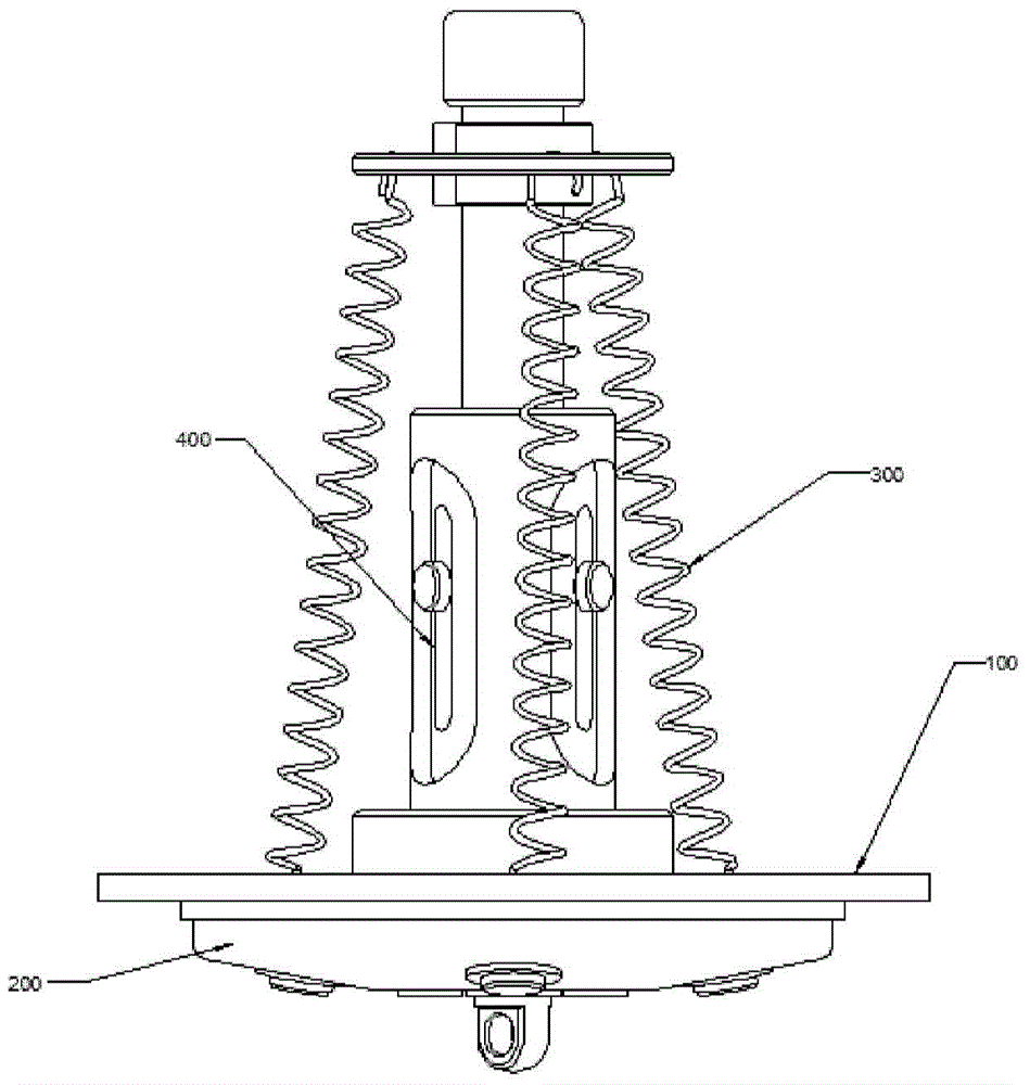
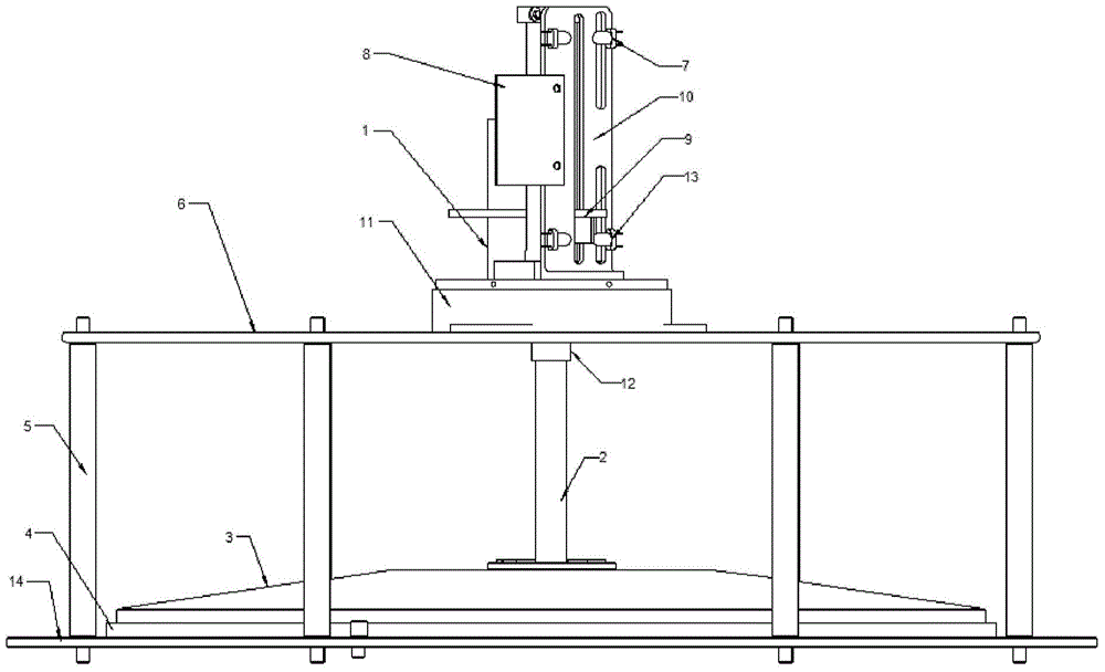
[0035] as attached figure 2 It shows a schematic block diagram of the photoelectric control valve structure of the aerostat of the present invention, image 3 is the front view of the valve in the closed state, Figure 4 yes image 3 A partial view of , where:

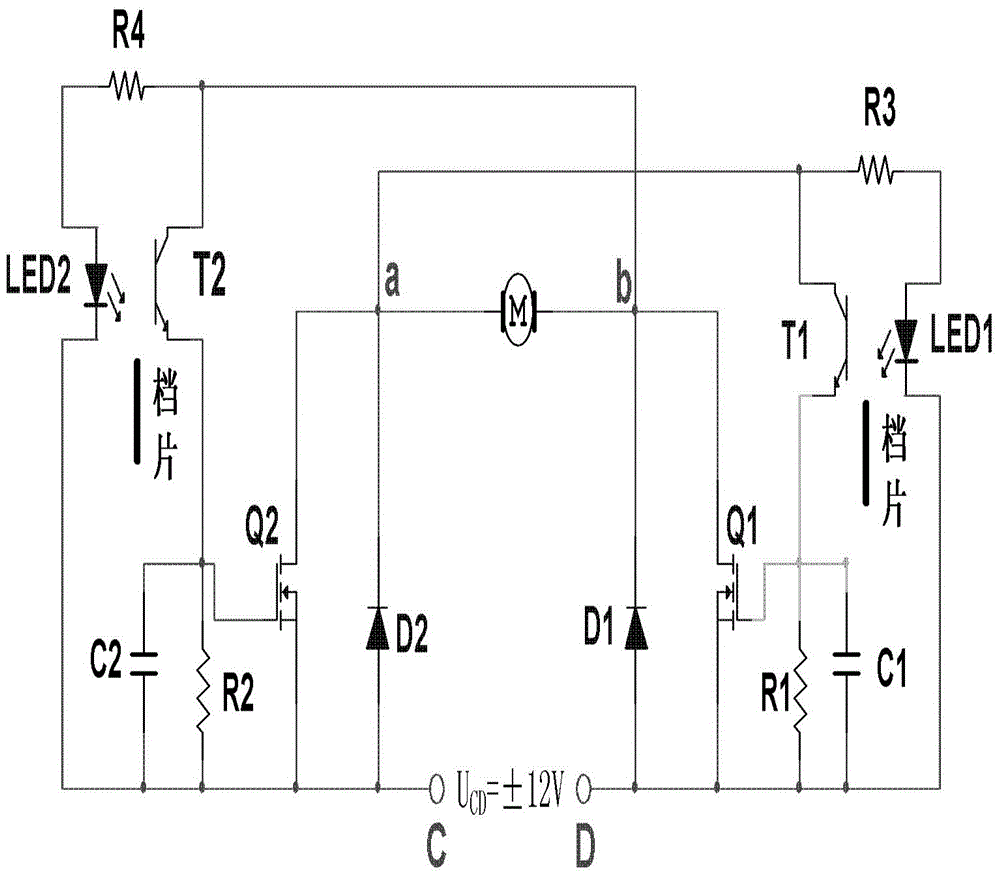
[0036] The aerostat photoelectric control valve includes: a valve cover 3, a sealing ring 4, a plurality of columns 5, a base 6, a control circuit 8, a valve body 14, an opening and closing mechanism part and a limit mechanism part; wherein: the valve body A circle of screw holes is ...


PUM


Abstract

The invention provides a photoelectric control valve of an aerostat. The photoelectric control valve of the aerostat comprises a valve cover, a seal ring, multiple columns, a base, a control circuit, a valve body, an opening-closing mechanism portion and a limiting mechanism portion, wherein the valve body is arranged on a bag body of the aerostat. The multiple columns are respectively located between the base and the valve body to enable the base and the valve body to be connected. The valve body is provided with a valve port and used for air in an air bag in the aerostat to be discharged out. An outer circle of the valve port is sleeved in an inner hole of the seal ring, and the valve cover covers the seal ring and the valve port and is in a sealed state. A flange structure of the lower end face of a lead screw of the opening-closing mechanism portion is fixed to the valve cover, and the lead screw is used for opening and closing the valve cover and enabling the valve cover to be away from and cover the valve port. A motor of the opening-closing mechanism portion is connected with the control circuit and controls lifting and downward moving of the valve cover in the vertical direction. The lead screw is provided with a threaded hole, a stopping block of the limiting mechanism portion is fixed to the lead screw through the threaded hole, and the stopping block vertically moves with the lead screw to block infrared light emitted by an upper limiting optical coupling assembly and a lower limiting optical coupling assembly of the limiting mechanism portion and cut off the control circuit and accordingly enables the motor to stopping running.

Description

technical field [0001] The invention relates to the technical field of aerostats, and relates to a photoelectrically controlled exhaust valve for aerostats, which can adjust the pressure difference between the inside and outside of the aerostat to make it safe and reliable and maintain its aerodynamic shape. Background technique [0002] An aerostat generally refers to a soft-structure aircraft whose specific gravity is lighter than air and relies on atmospheric buoyancy to lift into the air. The aerostat is composed of an airbag made of polymer composite material and various equipment and payloads arranged on the airbag. The airbag is filled with a buoyant gas with a density lower than that of air, and the density difference between the inside and outside of the airbag provides the aerostat buoyancy, thereby completing the lift-off of the aerostat. [0003] Aerostats generally include balloons and airships. The formed aerostats are launched from the ground. As the flight a...

Claims


Application Information

Patent Timeline
Patent Type & Authority Applications(China)
IPC IPC(8): F16K31/04F16K31/44
CPCB64B1/58F16K31/047
Inventor 何小辉连龙刚周江华王立祥
Owner ACAD OF OPTO ELECTRONICS CHINESE ACAD OF SCI
Why Eureka
Eureka Blog
Learn More