Dry-type deslagging system capable of adjusting cooling air
A technology of dry slag discharge and dry slag discharger, which is applied to lighting and heating equipment, etc., can solve the problems of reduced boiler operation efficiency and large cooling air volume, and achieves low renovation operation cost, improved operation efficiency, and reduced demand. Effect
- Summary
- Abstract
- Description
- Claims
- Application Information
AI Technical Summary
Problems solved by technology
Method used
Image


Examples
specific Embodiment approach 1
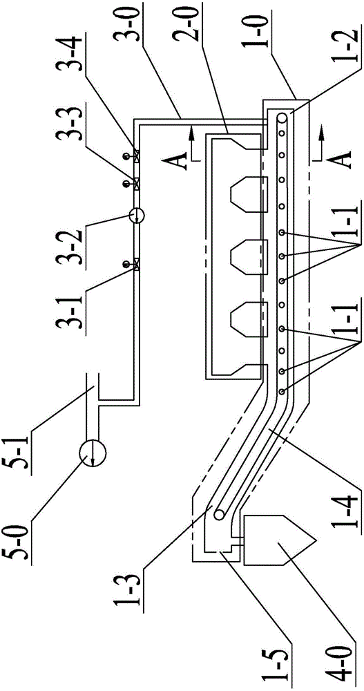
[0024] Specific implementation mode one: combine figure 1 and figure 2 Note that the dry slag discharge system with adjustable cooling air in this embodiment includes a dry slag discharge machine 1-0, a slag bin 4-0, a primary air inlet duct 5-1, a camera 2-5, and a primary fan 5-0 and several boilers 2-0, the primary fan 5-0 communicates with the primary air inlet duct 5-1,
[0025] The dry slag discharger 1-0 includes several cooling air manual adjustment butterfly valves 1-1, the conveyor belt 1-4, the horizontal section 1-2 and the ascending section 1-3, and the horizontal section 1-2 is connected with the ascending section 1-3 , the conveyor belt 1-4 is successively laid on the horizontal section 1-2 and the ascending section 1-3, and several cooling air manual adjustment butterfly valves 1-1 are arranged in the horizontal section 1-2 sequentially along the horizontal direction, above the horizontal section 1-2 Several boilers 2-0 are arranged vertically, and several ...
specific Embodiment approach 2
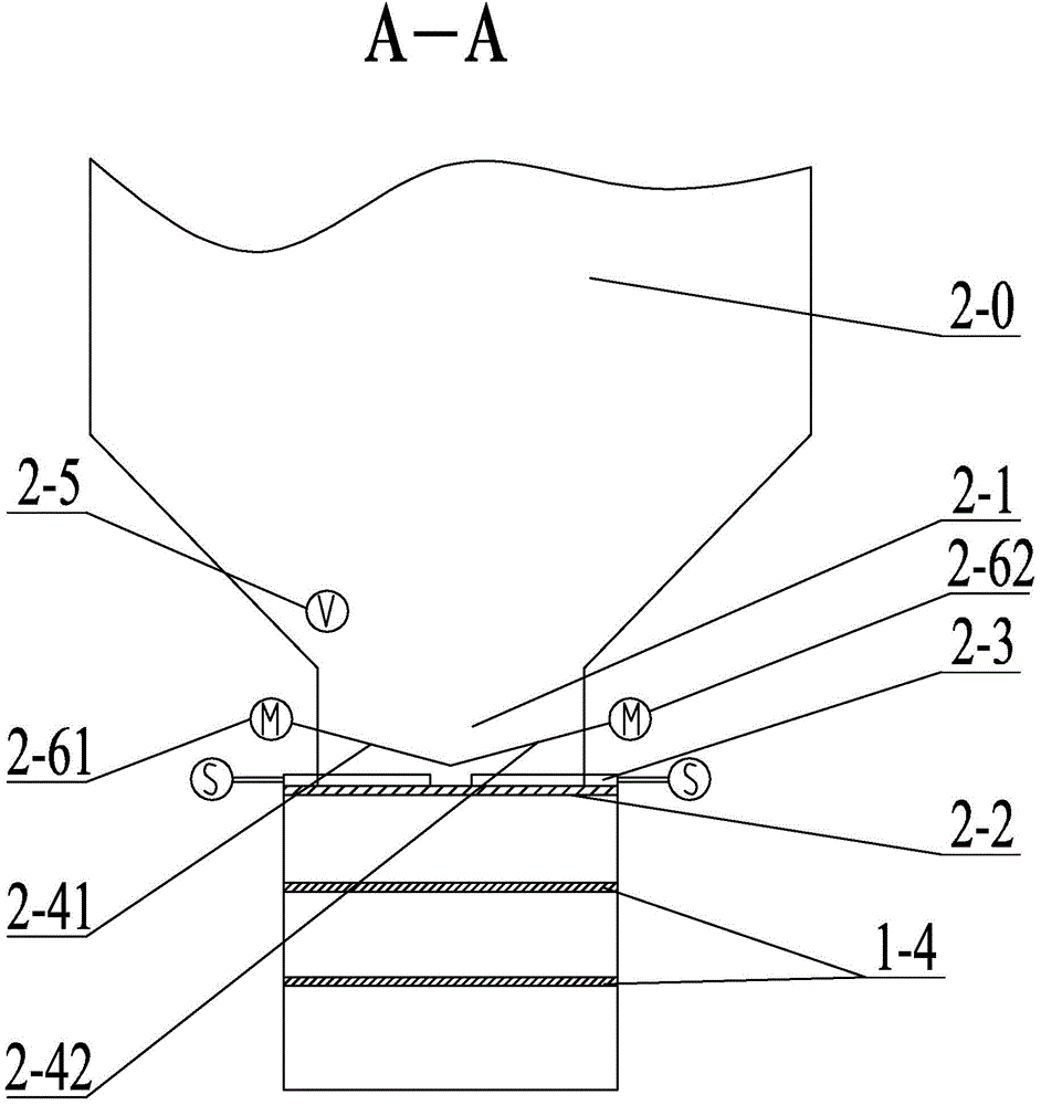
[0032] Specific implementation mode two: combination figure 1 and figure 2 Note that the cooling air regulating baffle in this embodiment has an inclination angle of 30° to the horizontal plane.
[0033] It is advisable that the inclination angle between the cooling air regulating baffle plate and the horizontal plane is 30°. Under this inclination angle, when the cooling air regulating baffle (hereinafter referred to as "adjusting baffle") is opened, no slag will accumulate on the upper surface of the regulating baffle; when the regulating baffle is closed, slag can be accumulated evenly on the regulating baffle . Thereby effectively ensuring that the slag falling onto the adjusting baffle can fall down under the action of gravity, and at the same time effectively ensuring that the adjusting baffle has sufficient strength to withstand the impact. If the inclination angle is too large, when the adjusting baffle is closed, The slag is mainly concentrated in the front secti...
specific Embodiment approach 3
[0035] Specific implementation mode three: combination figure 1 and figure 2 It is explained that the cooling air regulating baffle plate of this embodiment is slidably connected with the inner wall of the bottom end 2-1 of the furnace along the inclined direction.
[0036] The cooling air adjustment baffle is opened and closed by sliding connection, which effectively reduces the resistance of the cooling air adjustment baffle to open and close, especially the resistance when the cooling air adjustment baffle is closed, compared with the "hanging" opening and closing method. The opening and closing space of the cooling air adjustment baffle is saved, and the working load of the motor is effectively reduced.
[0037] The undisclosed technical features in this embodiment are the same as those in the first or second specific embodiment.
PUM
| Property | Measurement | Unit |
|---|---|---|
| The inside diameter of | aaaaa | aaaaa |
Abstract
Description
Claims
Application Information
 - R&D
- Intellectual Property
- Life Sciences
- Materials
- Tech Scout
- Unparalleled Data Quality
- Higher Quality Content
- 60% Fewer Hallucinations
Browse by: Latest US Patents, China's latest patents, Technical Efficacy Thesaurus, Application Domain, Technology Topic, Popular Technical Reports.
© 2025 PatSnap. All rights reserved.Legal|Privacy policy|Modern Slavery Act Transparency Statement|Sitemap|About US| Contact US: help@patsnap.com