Air-conditioner defrosting method

A technology for air conditioning and defrosting temperature, applied in the field of air conditioning defrosting, can solve the problems of low suction pressure of compressor, reduced heating comfort and system energy efficiency, insufficient defrosting energy source, etc., and achieve the effect of improving energy efficiency

Inactive Publication Date: 2014-11-05
QINGDAO HAIER AIR CONDITIONER GENERAL CORP LTD
View PDF7 Cites 33 Cited by
  • Summary
  • Abstract
  • Description
  • Claims
  • Application Information

AI Technical Summary

Problems solved by technology

[0003] Using the defrosting method of the air conditioner in the prior art, on the one hand, the unit takes heat from the indoor environment to melt the frost layer, causing the indoor heating environment to deteriorate; The energy mainly comes from the work of the compressor and the heat storage of the indoor

Method used


Image

  • Air-conditioner defrosting method
  • Air-conditioner defrosting method
  • Air-conditioner defrosting method

Examples


Embodiment 1

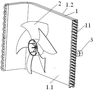
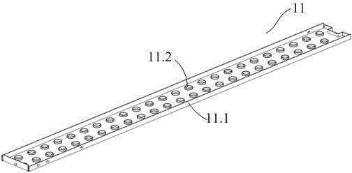
[0024] refer to figure 1 and figure 2 In this embodiment, the method for defrosting an air conditioner by using ultrasonic waves, the outdoor unit of the air conditioner includes a heat exchanger 1 , an outdoor fan 2 installed on the heat exchanger 1 , and an ultrasonic transducer 3 . Specifically, an ultrasonic energy transfer plate 11 is installed on the heat exchanger 1, holes are opened on the ultrasonic energy transfer plate 11, and the number of holes is consistent with the number of holes in the fins of the heat exchanger. process, that is, the expansion tube process is fixed on the copper tube of the heat exchanger, which can be arranged parallel to the fins. The ultrasonic energy transmission plate 11 has a side flange 11.1, and the ultrasonic transducer 3 is installed on its side wall flange 11.1. . The installation of the ultrasonic energy transmission plate 11 does not require additional processing procedures, and has a large contact area with the copper tube, w...

Embodiment 2

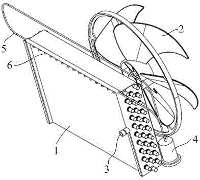
[0037] like figure 2 As shown, the difference from Embodiment 1 is that in step d of this embodiment, a pneumatic device is installed on the outdoor unit to blow off floating frost. Specifically, the pneumatic device includes an air pump 4 , an air collecting pipe 5 and a nozzle 6 arranged on the air collecting pipe 5 . When the frost layer is vibrated by the ultrasonic transducer 3 to become floating frost, the pneumatic device is activated, and the air flows through the air collecting pipe 5 and nozzle 6 to the heat exchanger 1 to automatically blow off the floating frost.

[0038] Similarly, in the step e, the time for the ultrasonic transducer 3 to stop running can be the same time as the closing time of the pneumatic device, or it can be earlier than the closing time of the pneumatic device, so that the pneumatic device can blow off the floating device more fully and thoroughly. Frost.

[0039] In order to improve the blow-off speed and the uniformity of the airflow, i...

Embodiment 3

[0042] like image 3 As shown, the difference from Embodiment 1 or 2 is that in step d of this embodiment, a mechanical brush is provided on the heat exchanger 1 to sweep off floating frost. Specifically, the mechanical sweeping brush includes a slideway 7 vertically fixed on the heat exchanger 1, a sweeping brush 8 that slides with the slideway 7 at both ends, a ferromagnetic block 9 fixed on the sweeping brush 8 and a fixed On the excitation coil 10 on the upper part of the heat exchanger 1 , the bristles of the sweeping brush 8 contact the fins of the heat exchanger 1 . When the mechanical sweeping brush is in the non-working state, the sweeping brush 8 is in the lower part of the heat exchanger 1 under the action of its own gravity. When the mechanical sweeping brush needs to work, the excitation coil 10 is energized to generate magnetism, and the ferromagnetic block 9 is attracted. Then pull the sweeping brush 8 to move upwards, sweep the fins, and finally reach the uppe...


PUM


Abstract

The invention provides an air-conditioner defrosting method. The method comprises the following steps that a, an air-conditioner operates in a heating mode; b, a defrosting temperature sensor on a heat exchanger is used for measuring the temperature T of a coil pipe, when the T is lower than the temperature Tes of a condensation point, an outdoor unit enters in a defrosting mode; c, an outdoor fan stops rotating, an ultrasonic transducer on the heat exchanger is turned on, and a frost layer on the heat exchanger is vibrated to be float frost; d, the float frost is actively removed to enable the float frost to disengage from the heat exchanger; e, when the defrosting temperature sensor on the heat exchanger detects that the temperature T of the coil pipe is higher than the temperature Tes of the condensation point, the ultrasonic transducer stops operation, the float frost active removing operation is stopped, the outdoor fan rotates forwardly, and the defrosting process is ended. In the heating operation process, the ultrasonic transducer is used for vibrating the frost layer into the float frost capable of falling off easily, then the float frost is actively removed, the frost layer can be quickly and effectively removed, the air-conditioner continuous operates without stopping, the normal heating operation of the system is not influenced, and the system energy efficiency can be better improved.

Description

technical field [0001] The invention belongs to the technical field of air conditioners, and in particular relates to a method for defrosting an air conditioner. Background technique [0002] The outdoor unit of the existing air source heat pump system has the problem of frosting during winter operation. The formation of the frost layer on the outdoor unit increases the surface thermal resistance of the outdoor unit and reduces the heat transfer coefficient of the outdoor unit. At the same time, the existence of the frost layer increases The resistance of air flowing through the outdoor unit is increased, the air flow rate is reduced, the heating performance of the unit is reduced, the heating capacity of the unit decreases, and the coefficient of heating performance decreases, which seriously affects the normal operation of the heat pump unit. In order to ensure the efficient operation of the air source heat pump, periodic defrosting is required. At present, inverter cycle...

Claims


Application Information

Patent Timeline
IPC IPC(8): F24F1/14F24F1/38
Inventor 袁俊军于世鹏王定远张明杰高希成
Owner QINGDAO HAIER AIR CONDITIONER GENERAL CORP LTD
Why Eureka
Try Eureka