Intermediate liquid discharge type efficient condensation system
A condensing system and high-efficiency technology, used in steam/steam condensers, lighting and heating equipment, etc., can solve the problems of low heat exchange efficiency, hindering fluid flow in the heat exchange pipeline, and unsatisfactory condensation effect. The effect of increasing heat transfer coefficient, efficient heat transfer and improving utilization rate
- Summary
- Abstract
- Description
- Claims
- Application Information
AI Technical Summary
Problems solved by technology
Method used
Image
Examples
Embodiment 1
[0016] This embodiment is an integral air-cooled condenser.
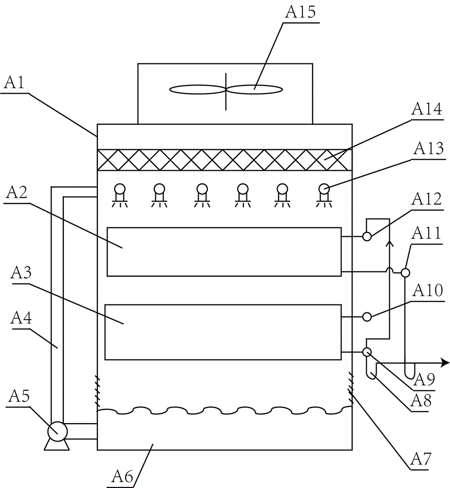
[0017] Such as figure 1 As shown, the embodiment of the present invention includes an A box A1 with an A air inlet A7 at the lower end and an A axial flow fan A15 installed at the upper end. A pre-stage heat exchanger A3 and A post-stage heat exchanger A2 are installed in A box A1. A Pre-stage outlet header A9. The front end of the heat exchange tube of the post-A heat exchanger A2 is connected to the post-A inlet header A12, and the rear end is connected to the post-A outlet header A11. The outlet header A9 of the pre-A stage is connected with the inlet-end header A12 of the post-A stage through pipelines, and is used to introduce the gas discharged from the pre-stage heat exchanger A3 of A into the post-stage heat exchanger A2.
[0018] The intermediate drain pipe connected to the header A9 of the front-stage outlet of A and the header A11 of the rear-stage outlet including the outlet header of the last-stage h...
Embodiment 2
[0022] This embodiment is an integral evaporative condenser.
[0023] still as figure 1 , on the basis of the first embodiment, this embodiment also includes the A sump A6 located under the A tank A1, the A water pump A5 connected to the A sump A6, and the A spray installed above the heat exchanger in the A tank A1. The shower pipe A13, wherein the A water pump A5 is connected with the A spray pipe A13 through the A upper water pipe A4. The A filler A14 between the A axial flow fan A15 and the A spray pipe A13 is also installed in the A box A1.
[0024] When used as an evaporative condenser, the A pre-stage heat exchanger A3 and the A post-stage heat exchanger A2 are preferably arranged in a vertical arrangement. The spray water flowing down from the upper heat exchanger flows through the lower heat exchanger and falls into the A sump A6.
[0025] The heat exchanger in A box A1 of the present invention can be figure 1 The two stages shown can also be more than three stages...
Embodiment 3
[0027] This embodiment is a split air-cooled condenser.
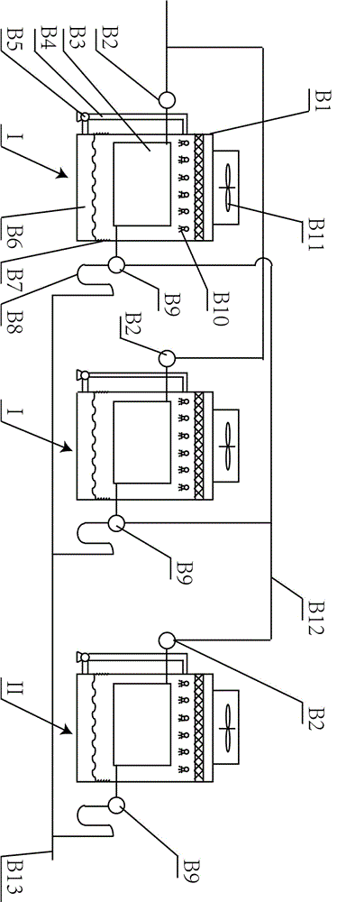
[0028] Such as figure 1 As shown, the embodiment of the present invention includes two pre-stage condensers I and one post-stage condenser II. Both the pre-stage condenser I and the post-stage condenser II have the following structure: the condenser includes a B box B1 with a B air inlet B7 at the lower end and a B axial flow fan B11 installed at the upper end. A heat exchanger B3 is installed in the box body B1, and the front end of the heat exchange tube of the heat exchanger B3 is connected to the inlet header B2, and the rear end is connected to the outlet header B9. Under the action of B axial flow fan B11, the cold air enters the B box B1 from the B air inlet B7 and flows through the heat exchanger B3, exchanges heat with the fluid in the heat exchange tube of the heat exchanger B3, and then discharges from the upper end of the B box B1.
[0029] The lead-out header B9 of the two pre-stage condensers I is connec...
PUM
 Abstract
Description
Claims
Application Information
 - R&D
- Intellectual Property
- Life Sciences
- Materials
- Tech Scout
- Unparalleled Data Quality
- Higher Quality Content
- 60% Fewer Hallucinations
Browse by: Latest US Patents, China's latest patents, Technical Efficacy Thesaurus, Application Domain, Technology Topic, Popular Technical Reports.
© 2025 PatSnap. All rights reserved.Legal|Privacy policy|Modern Slavery Act Transparency Statement|Sitemap|About US| Contact US: help@patsnap.com


