Numerical control machine tool guide rail molded surface rapid detection device and method

A detection device and a technology of numerically controlled machine tools, which are applied to measurement devices, optical devices, instruments, etc., can solve the problems of large measurement distance, difficulty in measuring straightness, and difficulty in achieving accuracy.

Active Publication Date: 2014-11-05
通用技术集团沈阳机床有限责任公司
View PDF3 Cites 2 Cited by
  • Summary
  • Abstract
  • Description
  • Claims
  • Application Information

AI Technical Summary

Problems solved by technology

It can measure the straightness of the guide rail in the vertical plane and the parallelism between two guide rails, but it is very difficult to measure the straightness in the horizontal plane. In addition, it is difficult to ensure the authenticity of the test results when the measurement distance is long; the cost of the autocollimator Compared with laser interferometer measurement, it is not easy to achieve high precision, generally 5μm / m
Because the light (LED light-emitting element) is not absolutely collimated in the air, the larger the measurement range, the greater the deviation, and the beam is susceptible to various disturbances during the propagation process, and it is a non-continuous measurement, and the result is very random. The laser interferometer has the characteristics of large measurement distance (40m), fast measurement speed (60m / min), high measurement accuracy (0.4μm / m), and can continuously measure and use a computer for data processing, display and printing, and The laser has good collimation and strong anti-interference ability, so it is more suitable for use in workshops and other places with poor environments. The disadvantage is that it is expensive, complicated to operate, and needs to be compensated
[0003] Based on the advantages and disadvantages of the above instruments, each instrument has its own scope of application, but none of them can quickly and accurately complete the measurement of straightness, flatness and parallelism at one time.

Method used


Image

  • Numerical control machine tool guide rail molded surface rapid detection device and method
  • Numerical control machine tool guide rail molded surface rapid detection device and method
  • Numerical control machine tool guide rail molded surface rapid detection device and method

Examples


Embodiment Construction

[0027] The patent will be further described below in conjunction with the accompanying drawings.

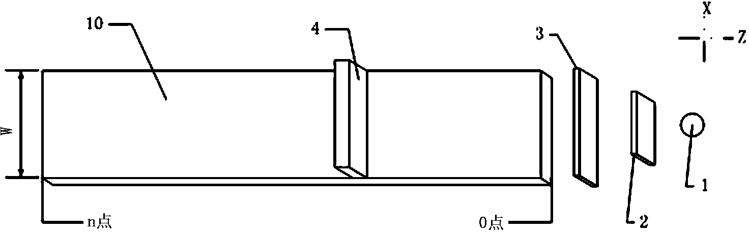
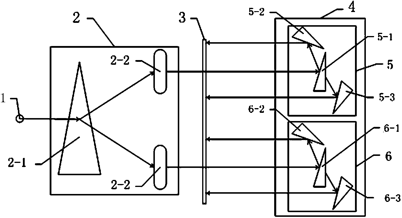
[0028] like figure 1 and figure 2 As shown, the rapid detection device for the guide rail profile of the CNC machine tool of this patent is composed of a laser emitter (1), a beam splitter (2), an optical component (4) movable on the guide rail and a laser receiver (3 )composition. The beam splitter 2 is composed of a Wollaston prism (2-1) and two objective lenses (2-2), and divides the laser light emitted by the laser transmitter into two beams of parallel light; the two beams of parallel light enter the optical beam in the optical component (4) respectively. In the lens group I (5) and the optical lens group II (6), each optical lens group divides the input light source of the laser into a refracted light and a reflected light and reflects them to the laser receiver (3) through the reflector.

[0029] The optical lens group (5) can test the movement deviation along the X ax...


PUM


Abstract

The invention relates to a numerical control machine tool guide rail molded surface rapid detection device. According to the numerical control machine tool guide rail molded surface rapid detection device, no strict rules for placement positions of a laser transmitter and a laser receiver exist, and a test result only depends on relative position relations between received lasers on the laser receiver and the initial test deviation of a test end guide rail. When a test is performed, the laser transmitter is well fixed, data are collected at equal intervals by moving an optical lens set, an auxiliary traction device can also be added, the optical lens set is moved at a constant speed, real-time high-density test data collection is achieved, and test precision is improved. The numerical control machine tool guide rail molded surface rapid detection device has the advantages of being accurate, reliable, rapid and the like, and can complete detection work of a plurality of test indexes at a time, and time and manpower are saved. Compared with the prior art, the numerical control machine tool guide rail molded surface rapid detection device has obvious accuracy and innovativeness.

Description

technical field [0001] The invention relates to a rapid detection device and detection method for a guide rail profile of a numerically controlled machine tool, belonging to the field of precision testing of a numerically controlled machine tool. Background technique [0002] From the present point of view, the measurement methods for the surface accuracy of machine tool guide rails mainly use level instruments, autocollimators and laser interferometers. The level instruments are simple to operate, easy to use, and low in cost, but the accuracy is low, generally only reaching 10~ 20μm / m. It can measure the straightness of the guide rail in the vertical plane and the parallelism between two guide rails, but it is very difficult to measure the straightness in the horizontal plane. In addition, it is difficult to ensure the authenticity of the test results when the measurement distance is long; the cost of the autocollimator Compared with laser interferometer, the measurement ...

Claims


Application Information

Patent Timeline
Patent Type & Authority Applications(China)
IPC IPC(8): G01B11/24
Inventor 李焱马晓波谢志坤仇健刘启伟王海滨葛任鹏
Owner 通用技术集团沈阳机床有限责任公司
Why Eureka
Try Eureka