
Protection method and system for unified power flow controller

A technology of a power flow controller and a protection system, applied in the field of protection methods and systems of a unified power flow controller, can solve the problems of no UPFC protection, complicated setting of values, little influence of AC protection, etc., and achieves clear protection configuration and method. Simple and reliable effects

Active Publication Date: 2014-11-05
NR ELECTRIC CO LTD +1
View PDF3 Cites 28 Cited by
  • Summary
  • Abstract
  • Description
  • Claims
  • Application Information

AI Technical Summary

Problems solved by technology

[0007] The analysis of the above literature only considered the impact of UPFC on line distance protection, and did not consider the impact on other such as line differential protection and directional elements, and did not involve the protection of UPFC's own equipment, the protection of the original AC system, and the protection of UPFC itself. When analyzing the impact of UPFC on distance protection, the above literature considers the parallel side of UPFC to be connected to the line in parallel, which will make the impact of UPFC on line protection complicated. For convenience and rationality, the parallel side will be connected to the busbar of the AC line as a branch of the AC busbar, which will have less impact on the AC protection and have the same control effect; In the end, keep the original protection sampling point unchanged, which will also make the setting of the protection setting complicated, which is not suitable for engineering applications, and the protection sampling point needs to be optimized

Method used

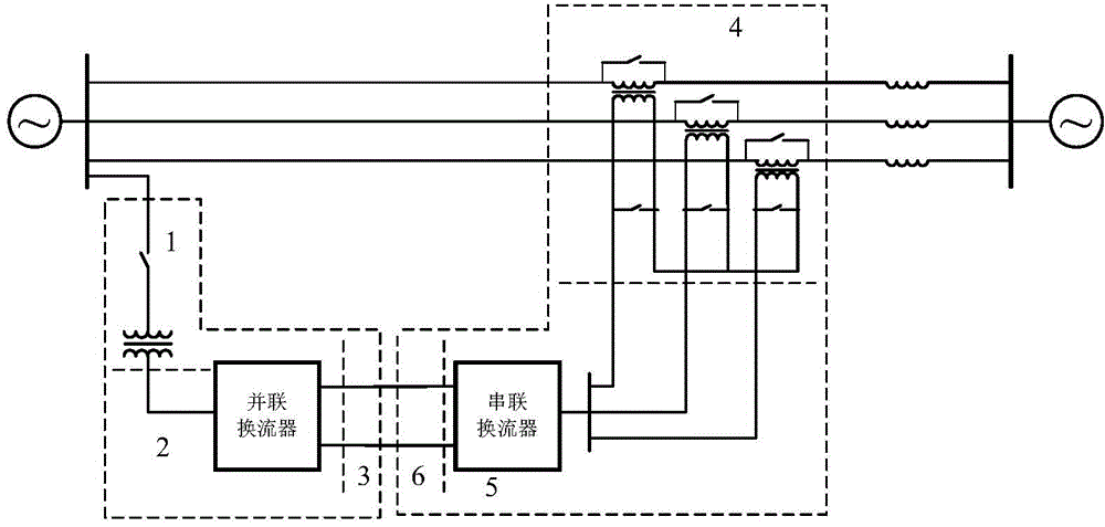

Image

  • Protection method and system for unified power flow controller
  • Protection method and system for unified power flow controller
  • Protection method and system for unified power flow controller

Examples


Embodiment Construction

[0030] Specific embodiments of the present invention will be described in detail below in conjunction with the accompanying drawings.

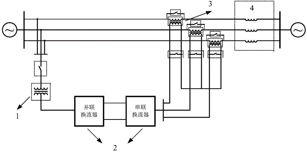
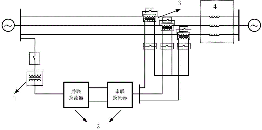
[0031] The equivalent diagram of the basic structure of the unified power flow controller is as follows: figure 1 As shown, 1 is a parallel transformer, 2 is a voltage source converter, 3 is a series transformer, and 4 is an AC line equivalent reactance. according to figure 1 The structure shown is not conducive to the wiring of the parallel side in engineering applications, and this connection has a greater impact on the protection of AC lines; for engineering applications, the parallel side of the unified power flow controller can be connected to the AC bus to reduce the The effects of line protection, such as figure 2 As shown, the structure is the same as figure 1 The structures shown are equivalent, and the control effect is the same.

[0032] The invention is based on figure 2 The structure shown provides a protection method and s...


PUM


Abstract

The invention provides a protection method and system for a unified power flow controller. The partitioning and layering method is adopted and includes the steps that the unified power flow controller is firstly partitioned according to the number of current converters; partition protection is carried out on each current converter area according to an alternating current protection area, a converter valve protection area and a direct current pole protection area; meanwhile, layered protection is carried out on the converter valve areas according to a converter valve layer and a valve element layer. The protection system is characterized in that according to the characteristic that a series connection side transformer is connected into a line in series, a PT is additionally arranged on the line to enable a series connection transformer primary winding to be arranged between the PT and a CT of an original line, a series connection transformer line side winding is brought into a line protection range, and meanwhile the additionally-arranged line PT is adopted for line protection. The protection method and system are simple and reliable, all areas of a UPFC device are covered, UPFC protection is matched with original alternating current system protection, the protected ranges are intersected, it is guaranteed that protected dead zones do not exist, and the motion reliability of the integral system is improved.

Description

technical field [0001] The invention belongs to the field of flexible power transmission in power systems, and in particular relates to a protection method and system for a unified power flow controller. Background technique [0002] With the interconnection of large-scale power systems and the use of various new equipment, the scale and complexity of the power system have also increased while making power generation and transmission more economical and efficient; coupled with a large number of distributed power generation systems connected to the grid , so that the traditional fixed power flow transmitted from the transmission network to the distribution network is reversed; the continuous growth of user load requires power flow control means to improve the existing power transmission capacity; the complex power exchange between the booming smart grid and the power market requires Frequent flow optimization control. [0003] The unified power flow controller, also known as...

Claims


Application Information

Patent Timeline
IPC IPC(8): H02H7/00H02H7/20H02H7/12H02J3/00
Inventor 潘磊刘超田杰沈全荣李海英卢宇董云龙
Owner NR ELECTRIC CO LTD
Learn More