
Radio frequency receiver and receiving method

A radio frequency receiver and receiving channel technology, applied in the field of communication, can solve the problem that multiple frequency synthesizers cannot be integrated in a single chip, etc.

Active Publication Date: 2014-11-05
HUAWEI TECH CO LTD
View PDF5 Cites 25 Cited by
  • Summary
  • Abstract
  • Description
  • Claims
  • Application Information

AI Technical Summary

Problems solved by technology

[0010] An embodiment of the present invention provides a radio frequency receiver to solve the problem that the prior art cannot integrate multiple frequency synthesizers into a single chip

Method used


Image

  • Radio frequency receiver and receiving method
  • Radio frequency receiver and receiving method
  • Radio frequency receiver and receiving method

Examples


Embodiment 1

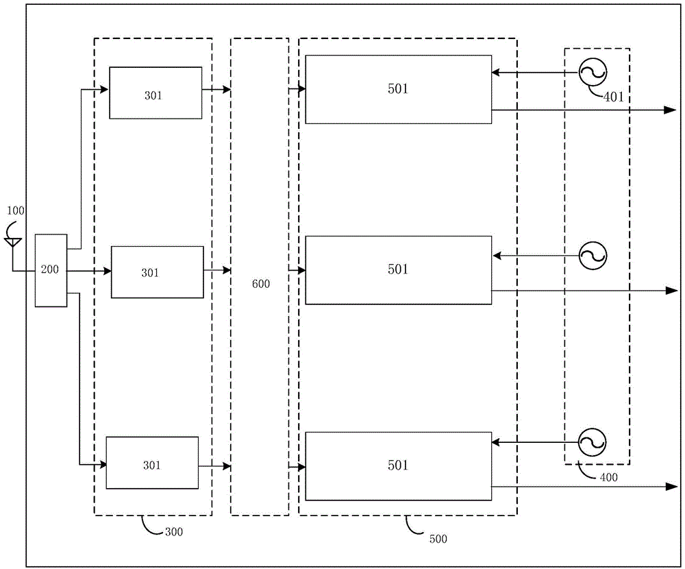
[0065] like image 3 As shown, Embodiment 1 of the present invention provides a radio frequency receiver, including:

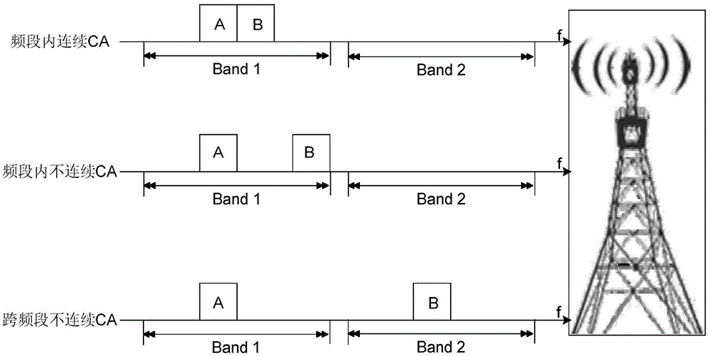
[0066] The antenna 100 is configured to receive a radio frequency signal, for example, a radio frequency signal transmitted by a base station in a wireless network, wherein the radio frequency signal is a multi-carrier carrier aggregation signal. Those skilled in the art should know that in practical applications, multi-carrier carrier The aggregation method includes at least one of continuous carrier aggregation within a frequency band, discontinuous carrier aggregation within a frequency band, and discontinuous carrier aggregation across frequency bands. For details, see figure 1 Several typical multi-carrier aggregation modes are shown. Those skilled in the art should know that when the radio frequency receiver in the embodiment of the present invention is integrated into a chip, the antenna 100 is generally not included in the chip.

[0067] A frequency ...

Embodiment 2

[0095] Based on the radio frequency receiver described in Embodiment 1, such as Figure 12 As shown, the embodiment of the present invention also provides a method for receiving radio frequency signals of multi-carrier aggregation, including the following steps:

[0096] S1. Receive a radio frequency signal, where the radio frequency signal is a multi-carrier carrier aggregation signal;

[0097] S2. Perform frequency band separation on the radio frequency signal to obtain at least one frequency band signal and output it, wherein each frequency band signal includes at least one carrier in the multi-carrier;

[0098] S3. Filter and amplify the at least one frequency band signal respectively to obtain at least one processed signal;

[0099] S4, generating a plurality of oscillating signals;

[0100] S5. Selectively receive a processed signal including a target carrier from the at least one processed signal, and receive an oscillating signal corresponding to the target carrier f...


PUM


Abstract

The invention discloses a radio frequency receiver and a receiving method. The receiving method comprises the following steps of: carrying out frequency band separation on a radio frequency signal with multi-carrier aggregation so as to obtain at least one frequency band signal and output; respectively carrying out filtering and amplification processing on the at least one frequency band signal so as to obtain at least one processing signal; generating a plurality of oscillation signals; selectively receiving a processing signal comprising target carrier from the at least one processing signal, receiving one oscillation signal corresponding to the target carrier, selectively selecting a frequency dividing ratio from a plurality of frequency dividing ratios, carrying out frequency division on the oscillation signal corresponding to the frequency dividing ratio to obtain a local oscillation signal, carrying out frequency mixing on the received processing signal comprising the target carrier by utilizing the local oscillation signal so as to obtain a frequency mixing signal, and generating a baseband signal corresponding to the target carrier based on the frequency mixing signal, herein mutual interference between the oscillation signals is restrained through respectively selecting the frequency dividing ratio.

Description

technical field [0001] The invention relates to the communication field, in particular to a radio frequency receiver and a receiving method thereof. Background technique [0002] At present, in order to increase the communication bandwidth and achieve higher user data throughput, in the advanced long-term evolution technology (Long-Term Evolution–Advanced, LTE-A), the carrier aggregation (Carrier Aggregation, CA) technology, CA technology The principle of CA is to carry user communication data on multiple carriers for communication; however, the introduction of CA technology has had a great impact on the original RF receiver solution. [0003] In the 3GPP (Third Generation Partnership Project) protocol R10 (Release 10, version 10), the following three CA application scenarios are defined, such as figure 1 Shown: [0004] Intra-band continuous CA (intra-band, contiguous CA); [0005] Discontinuous CA (intra-band, non-contiguous CA) within the frequency band; [0006] Inte...

Claims


Application Information

Patent Timeline
IPC IPC(8): H04B1/16
CPCH04B1/0057H04B1/006H04B1/126H04J1/12H04W88/06
Inventor 易岷梁建朱年勇
Owner HUAWEI TECH CO LTD
Learn More