Mechanical pencil

A technology for mechanical pencils and refills, applied to mechanical pencils, writing connectors, printing, etc., to achieve the effects of easy loading and operation, reduced number of parts, and ease of use

Active Publication Date: 2014-11-05
MITSUBISHI PENCIL CO LTD
View PDF7 Cites 2 Cited by
  • Summary
  • Abstract
  • Description
  • Claims
  • Application Information

AI Technical Summary

Problems solved by technology

Therefore, it is possible to always write with approximately the same line width

Method used


Image

  • Mechanical pencil
  • Mechanical pencil
  • Mechanical pencil

Examples


Embodiment Construction

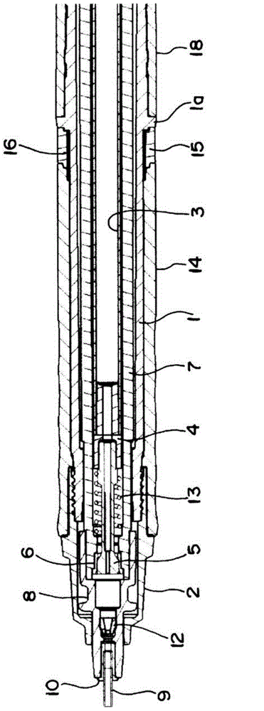
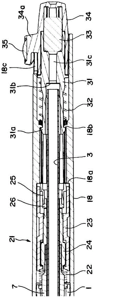
[0029] The mechanical pencil according to the present invention will be described based on an embodiment in which the lead is rotationally driven according to writing pressure. In addition, although the same parts are denoted by the same symbols in each of the drawings shown below, depending on the situation of the drawings, symbols may be attached to typical parts in some drawings, and the detailed structure The description will refer to symbols attached to other drawings.

[0030] figure 1 and figure 2 It is used to divide it into the first half and the second half to illustrate the overall structure of the mechanical pencil. First, in figure 1 Among them, on the front end portion of the front shaft 1 constituting the shaft cylinder, the front shaft 1 is detachably mounted through a threaded joint end member (mouth first member, base member) 2 . Then, a cylindrical core box 3 is accommodated along the axial cores of the above-mentioned front axle 1 and the following rea...


PUM


Abstract

A rotational drive mechanism utilized for a mechanical pencil is configured so that a cam structure is simple, the number of parts is reduced, and the easiness of assembly of the rotational drive mechanism is ensured. A large number of cam surfaces (24a, 24b) which continue in an annular shape are formed on the upper and lower surfaces of a rotary cam (24) which forms a rotational drive mechanism (21), the upper and lower surfaces perpendicularly intersecting the axial direction of the rotary cam (24). An axially long elastic member (23b) is integrally formed on a holder member (23) which supports the rotary cam (24) in a rotatable manner. First and second stationary cams (23c, 23d) which are provided with a small number of cam surfaces are disposed at the base end and front end of the elastic member so as to face each other and to sandwich the upper and lower cam surfaces (24a, 24b) of the rotary cam (24). The rotary cam (24) is configured so that the rotary cam (24) is rotated and driven in one direction when the writing lead is moved forward and backward in the axial direction by writing pressure applied to the writing lead, and that the rotational motion of the rotary cam (24) is transmitted to the writing lead.

Description

field of invention [0001] The present invention relates to a mechanical pencil capable of rotating, for example, a refill (replacement refill) by utilizing writing pressure, and particularly relates to an improvement of a rotation drive mechanism for rotating and driving a refill or the like. Background technique [0002] As is well known in the mechanical pencil, there is a problem that the thickness of the stroke line changes because the pen core decreases on one side as the writing progresses. [0003] Therefore, the applicant of this case previously proposed a mechanical pencil with the following rotary drive mechanism, which can use the writing pressure applied to the pen core to slowly rotate the pen core in one direction. This technology is disclosed in the patent Literature 1 and 2 etc. [0004] According to this mechanical pencil, when writing is performed with the shaft barrel tilted to the writing surface (paper surface), for example, about 40 to 80 degrees, the ...

Claims


Application Information

Patent Timeline
Patent Type & Authority Applications(China)
IPC IPC(8): B43K21/00B43K21/16
CPCB43K21/22B43K21/06B43K29/02B43K21/16B43K23/008B43K21/006B43K21/00B43K23/02B43K29/00
Inventor 井泽弘壮守本大作
Owner MITSUBISHI PENCIL CO LTD
Why Eureka
Try Eureka