

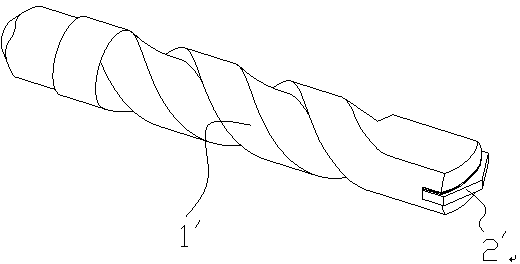
Automatic drill bit welding machine
A technology for automatic welding machines and drills, which is applied in welding equipment, high-frequency current welding equipment, metal processing equipment, etc., and can solve problems such as adverse effects on the body of operators, high labor intensity, and eye injuries
- Summary
- Abstract
- Description
- Claims
- Application Information
AI Technical Summary
Problems solved by technology
Method used
Image

Examples
Embodiment Construction
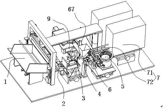
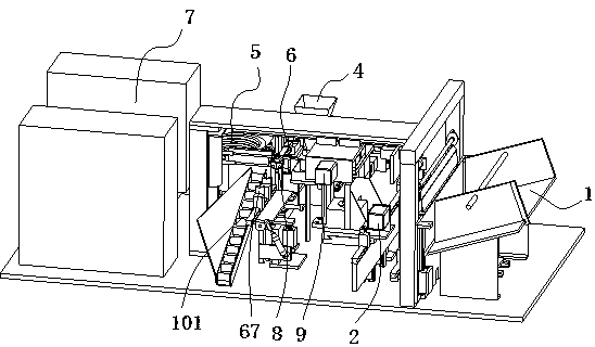
[0034] Such as Figure 2-3 As shown, an automatic drill bit welding machine mainly includes a single feeding mechanism for the drill bit body connected to each other 1, a horizontal alignment device for the incision of the drill bit body 2, an automatic copper strip feeding device 3, a solder adding mechanism for welding 4, and an alloy sheet The material mechanism 5, the precise alignment mechanism 6 of the alloy sheet and the drill body, the high-frequency heating device 7 and the alloy sheet calibration device 8 after welding.
[0035] Such as Figure 4 As shown, the drill body single feeding mechanism 1 sends the drill body to be processed into the drill body incision horizontal alignment device 2 in a single horizontal manner. The single feeding mechanism 1 of the drill body includes a hopper 11 with a bottom panel 111 inclined inwardly, and a push plate 12 is installed on the inner side plate 112 close to the hopper 11, and the push plate 12 is movably installed on the ...
PUM
 Abstract
Description
Claims
Application Information