A Combined Ceramic Bottom Pin of Spinning Frame
A spinning frame, combined technology, applied in spinning frames, textiles and papermaking, drafting equipment, etc., can solve the problems of poor casting surface roughness, difficulty in ensuring product uniformity, and affecting spinning quality, etc. The effect of reducing Cv% value, improving evenness quality and improving spinning quality
- Summary
- Abstract
- Description
- Claims
- Application Information
AI Technical Summary
Problems solved by technology
Method used
Image
Examples
Embodiment 1
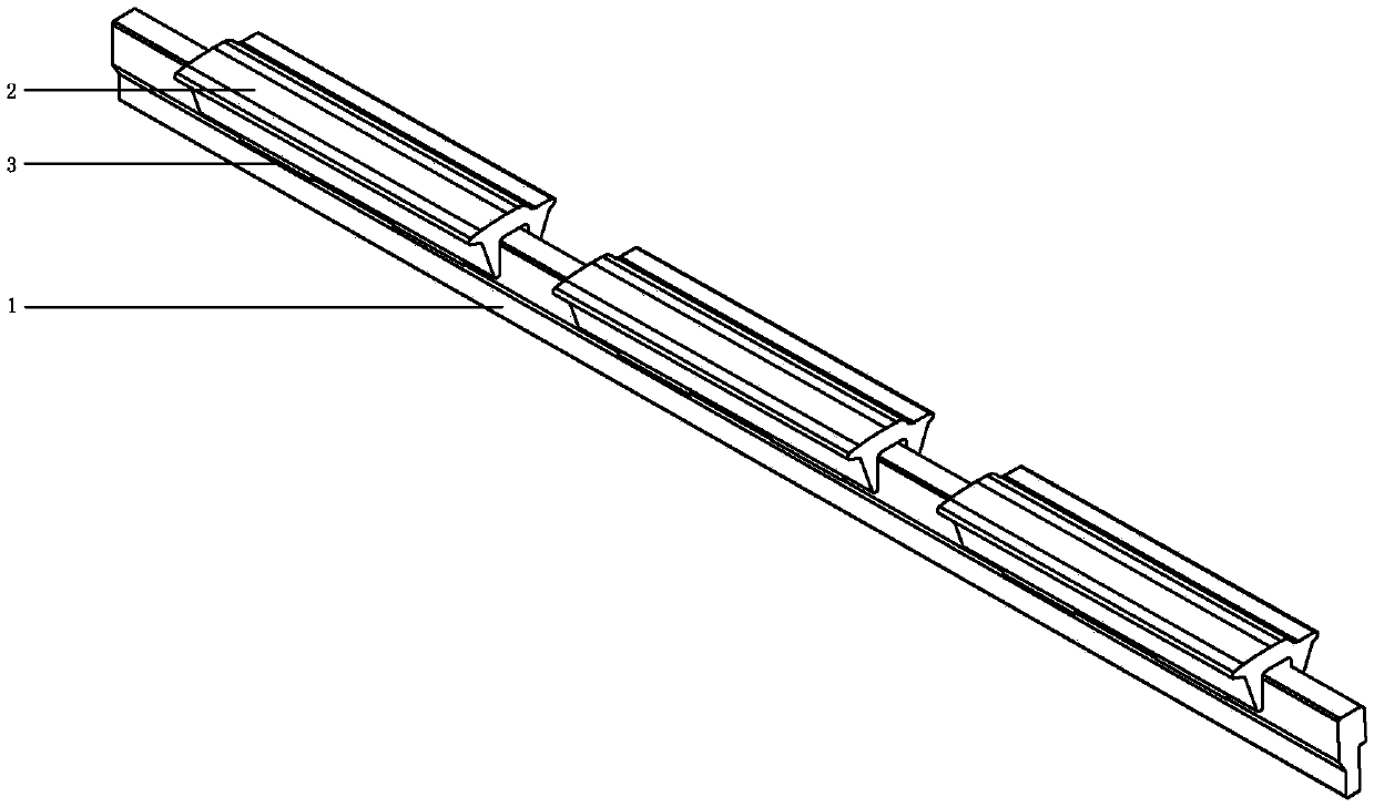
[0045] A combined spinning frame ceramic lower pin, such as figure 1 As shown, the ceramic lower pin includes a support mounting part 1 and a supporting lower apron running part 2, wherein the ceramic lower pin also includes a connecting fastening for connecting the supporting mounting part 1 and the supporting lower apron running part 2 together. piece 3;
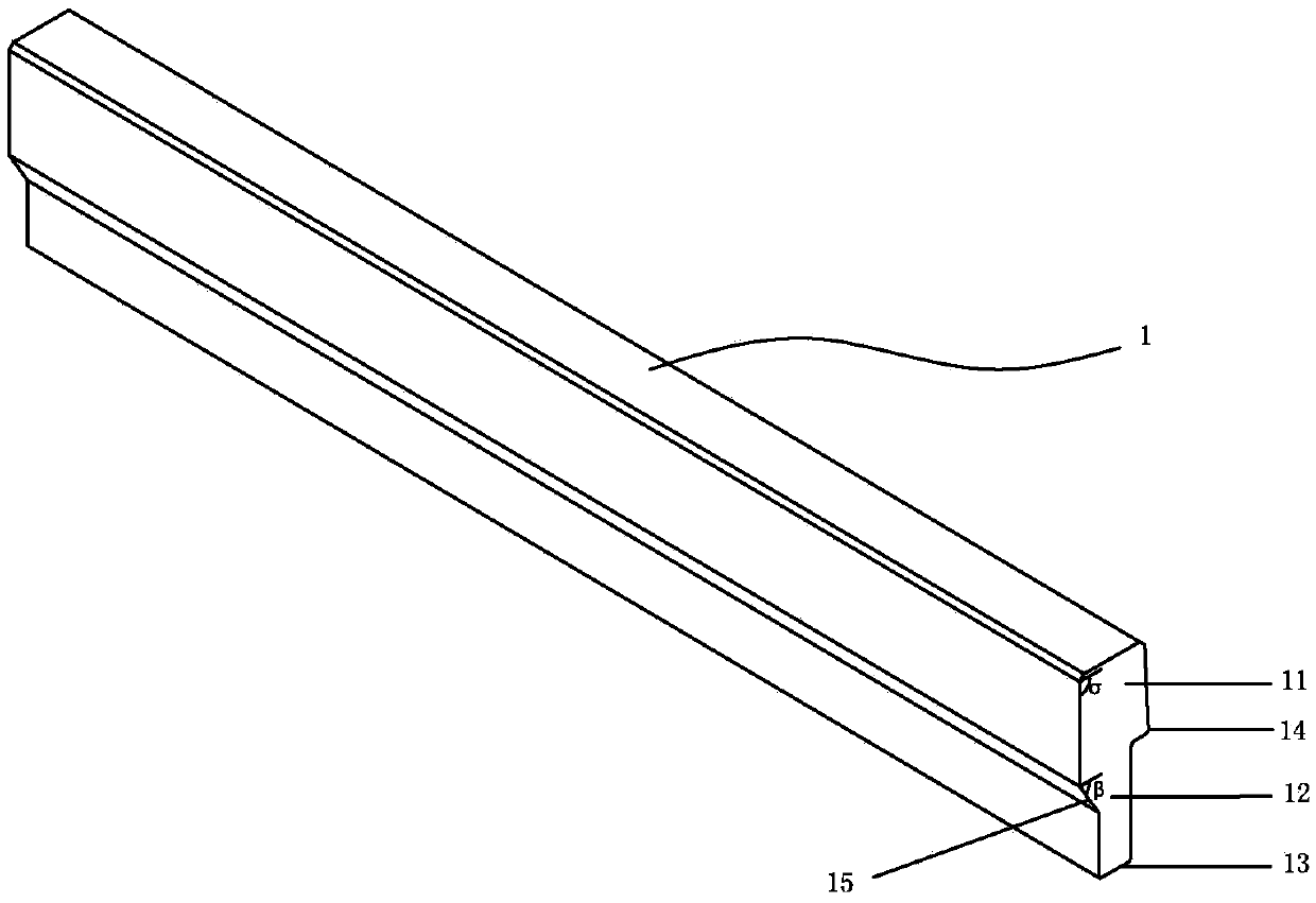
[0046] Such as figure 2 As shown, the support mounting part 1 is integrally formed by a self-locking installation slope part 11, a self-positioning bevel part 12 and a free end part 13; Angle trapezoidal face same side notched angle waist constitutes self-locking installation inclined plane 14; The random section of described self-positioning bevel part 12 is the right-angled trapezoidal face of identical shape, described right-angled trapezoidal face same side oblique waist constitutes self-positioning beveled face 15 ; The waist of the self-locking installation slope 14 forms a σ angle of 91° with the top; the slope w...
Embodiment 2
[0051] A combined spinning frame ceramic lower pin, such as Figure 6 and Figure 7 As mentioned above, the ceramic lower pin is different from Example 1 in that the material supporting the lower apron running part 2 is clay ceramics; Figure 8 As shown, the top of the support mounting part 1 is provided with a tapered positioning groove 16; as Figure 9 As shown, the inner side of the top of the connecting fastener 3 is provided with a positioning conical protrusion 32 matched with the tapered positioning groove 16; the bottom side of the connecting fastener 3 is provided with a clip 33; the clip 33 can be stuck in the On the self-positioning bevel part 12; the snap feet 33 have elasticity; and the waist of the self-locking installation bevel 14 forms a σ angle of 95° with the top; the slant waist of the self-positioning bevel surface 15 forms a β angle of 75° with the top; connection The fastener 3 is made of elastic steel with a certain thickness.
Embodiment 3
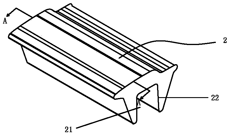
[0053] A combined ceramic lower pin for spinning frame. The difference between the ceramic lower pin and Example 2 is that the support mounting part 1 is cold-drawn flat steel, the size of which is 420×3.5×20 mm, and the material is 45# steel; The shape of any cross-section of the lower apron running part 2 is the same, and the upper surface of the cross-section is a combined shape of a section of straight line and a section of curve. The length of the part is 5mm; the length of a curved part connected with a straight part is correspondingly 19mm, and the distance A1 between the highest point and the leading edge of a straight part is 10.23mm; the distance between the highest point and the tail end of the lower pin of the rubber ring The distance C1 is 13.77 mm; the height difference H1 between a curved part and a straight part is 3.3 mm; the total height H2 of the section is 5-26.25 mm; the total width is 20 mm; The through groove 21 has a depth of 13.6 mm and a width L3 of 3...
PUM
| Property | Measurement | Unit |
|---|---|---|
| length | aaaaa | aaaaa |
| length | aaaaa | aaaaa |
| thickness | aaaaa | aaaaa |
Abstract
Description
Claims
Application Information
 - R&D
- Intellectual Property
- Life Sciences
- Materials
- Tech Scout
- Unparalleled Data Quality
- Higher Quality Content
- 60% Fewer Hallucinations
Browse by: Latest US Patents, China's latest patents, Technical Efficacy Thesaurus, Application Domain, Technology Topic, Popular Technical Reports.
© 2025 PatSnap. All rights reserved.Legal|Privacy policy|Modern Slavery Act Transparency Statement|Sitemap|About US| Contact US: help@patsnap.com


