
Transmission device for high-pressure production line caterpillar-tractor

A transmission device and production line technology, applied in the field of tractors, can solve problems such as the unbalanced force on the main shaft of the upper turbine box, and achieve the effects of solving the unbalanced force, reducing the bearing damage rate and reducing the maintenance cost.

Inactive Publication Date: 2014-11-12
JIANGSU ZHONGXING CABLE
View PDF6 Cites 0 Cited by
  • Summary
  • Abstract
  • Description
  • Claims
  • Application Information

AI Technical Summary

Problems solved by technology

[0003] The purpose of the present invention is to overcome the shortcomings of the above-mentioned prior art and provide a transmission device for crawler tractors in a high-voltage production line, so that the two disk bearings in the main shaft of the upper turbine box are subjected to the same force as the external support points, which solves the problem of insufficient force on the main shaft of the upper turbine box. balance problem

Method used


Image

  • Transmission device for high-pressure production line caterpillar-tractor
  • Transmission device for high-pressure production line caterpillar-tractor

Examples


Embodiment Construction

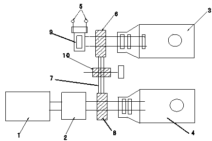
[0011] Such as figure 1 As shown, a high-voltage production line crawler tractor transmission device according to the present invention includes a DC motor 1, a gearbox 2, an upper turbine box 3 and a lower turbine box 4, and the main shafts of the DC motor 1 and the lower turbine box 4 Connected, a gearbox 5 is provided on the main shaft between the DC motor 1 and the lower worm case 4, and a lower synchronous pulley 6 is provided on the main shaft between the gearbox 5 and the lower worm case 4, and the synchronous Belt 7 is connected with upper synchronous pulley 8; Upper synchronous pulley 8 is arranged on the main shaft of upper worm case 3 above lower worm case 4; The two disk bearings in the main shaft of the upper turbine box 3 are the same anti-pull supporting device 9 as the external support point.

[0012] A belt pressure pulley 10 is provided at the synchronous belt 7 between the upper and lower synchronous wheels 8 and 6 .

[0013] Two pull rings 11 are arranged...


PUM


Abstract

The invention discloses a transmission device for a high-pressure production line caterpillar-tractor. The transmission device comprises a direct-current motor, a gearbox, an upper turbine box and a lower turbine box. The direct-current motor is connected with a main shaft of the lower turbine box. The gearbox is arranged on the portion, between the direct-current motor and the lower turbine box, of the main shaft. A lower synchronous belt pulley is arranged on the portion, between the gearbox and the lower turbine box, of the main shaft. The portion above the lower synchronous belt pulley is connected with an upper synchronous belt pulley through a synchronous belt. The upper synchronous belt pulley is arranged on the main shaft of the upper turbine box located above the lower turbine box. A counter-pull supporting block enabling stress on two plate bearings in the main shaft of the upper turbine box and stress on the external supporting point to be equal is additionally installed on the main shaft, outside the upper synchronous belt pulley, of the upper turbine box. According to the transmission device, the counter-pull supporting block is increased, the stress on the two plate bearings in the main shaft of the upper turbine box is the same as the stress on the external supporting point, and therefore the problem that the stress is not balanced is solved; by means of the improvement, the damage rate of the bearings are greatly reduced compared with that in the past, and the maintenance cost is greatly reduced.

Description

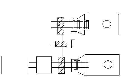
technical field [0001] The invention belongs to the field of tractors, and in particular relates to a transmission device of a crawler tractor for a high-voltage production line. Background technique [0002] Originally, the upper and lower turbine boxes were driven by a DC motor and gearbox, and then the upper turbine box was driven by a synchronous belt to synchronize the upper and lower turbine boxes. The structure is as follows: figure 1 shown. The disadvantages are: due to the unbalanced force point of the upper turbine main shaft, the external synchronous pulley is under too much downward pull, which damages the outer bearing of the two middle disc bearings, and at the same time, the internal gear is broken, requiring maintenance. It is cumbersome and increases the cost. Contents of the invention [0003] The purpose of the present invention is to overcome the shortcomings of the above-mentioned prior art and provide a transmission device for crawler tractors in a ...

Claims


Application Information

Patent Timeline
Patent Type & Authority Applications(China)
IPC IPC(8): F16H37/02F16H57/02
CPCF16H37/02F16H57/021F16H2057/0213
Inventor 李瑞
Owner JIANGSU ZHONGXING CABLE
Learn More