Standard fastener detection conveying and detection device

A technology for standard fasteners and detection devices, which is applied in the direction of measuring devices, optical devices, and optical testing for flaws/defects, etc. It can solve the problems of inability to detect thread pitches, fewer detection mechanisms, and narrow adaptation ranges, and achieve easy processing and production , easy adjustment and simple structure

Inactive Publication Date: 2014-11-12
CHONGQING YINGQUAN STANDARD PARTS
View PDF3 Cites 3 Cited by
  • Summary
  • Abstract
  • Description
  • Claims
  • Application Information

AI Technical Summary

Problems solved by technology

[0006] First, the detection mechanism can detect fewer functions, and the scope of application is narrow
For example, thread detection can only detect the presence or absence of tapping, whether the length is sufficient, etc., but cannot detect whether the thread pitch and tooth shape are qualified, and the detection accuracy is not high, and there are still high defective products after detection
[0007] Second, a detection device can only detect one type of part. Standard fastener companies generally produce a variety of parts, such as screws, nuts, bolts, etc. If automatic detection devices are used, multiple sets of different detection devices must be purchased. Device testing, enterprise production investment increased
The detection disk of the existing detection device needs to make a detection disk corresponding to each specification of the part, and the corresponding detection disk should be replaced when the parts of different specifications are to be tested, which causes problems such as increased cost of the detection device and low detection efficiency
[0009] Fourth, the existing detection device only detects defective products, and 1-2 workers are required to pack the parts that pass the test. The problems of work efficiency and labor cost of the enterprise have not been completely resolved.

Method used


Image

  • Standard fastener detection conveying and detection device
  • Standard fastener detection conveying and detection device
  • Standard fastener detection conveying and detection device

Examples


Embodiment Construction

[0032] Below in conjunction with accompanying drawing and embodiment the present invention will be further described:

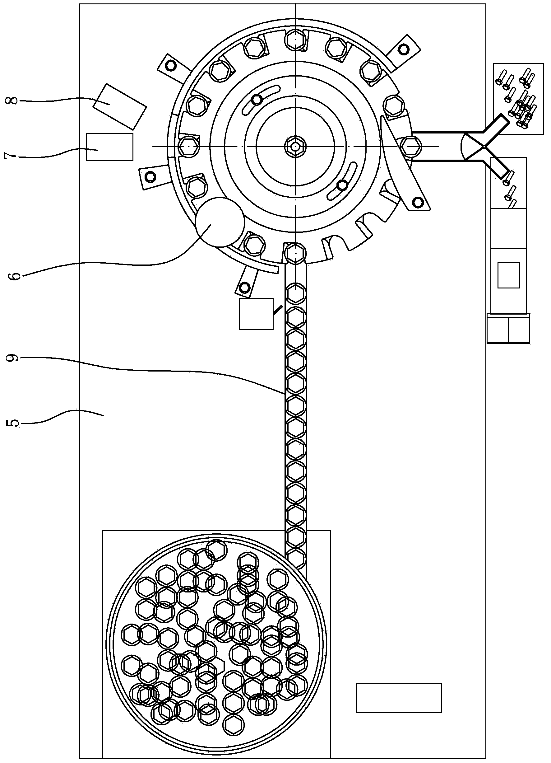
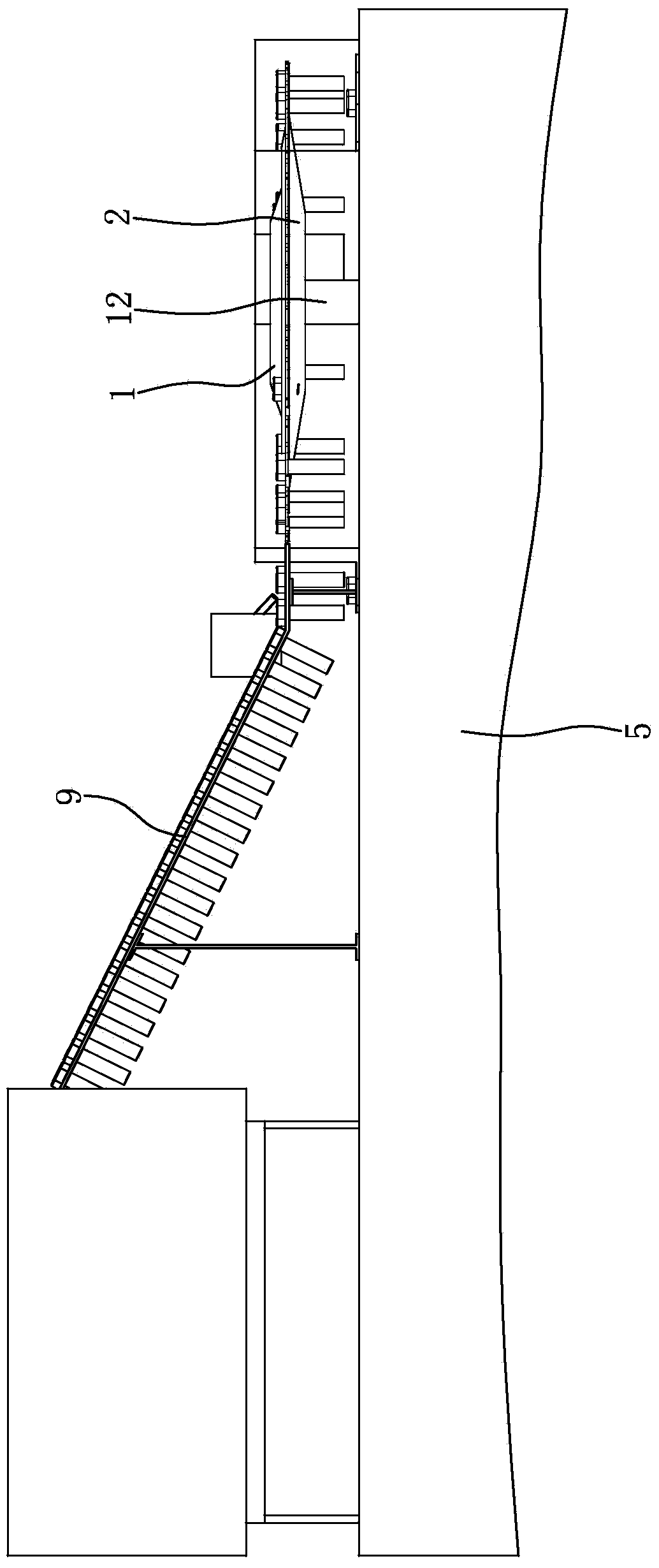
[0033] Such as figure 1 , figure 2 , Figure 5As shown, the indexing turntable is arranged on the machine platform 5 and consists of a moving plate 1 and a fixed plate 2 . The first CCD camera 6 is arranged above the edge of the indexing turntable, and the lens of the first CCD camera 6 faces downwards, and the second CCD camera 7 and the third CCD camera 8 are set beside the indexing turntable, and the second CCD The camera 7 is close to the third CCD camera 8, and there is an angle of about 30° between the second CCD camera 7 and the third CCD camera 8, and the lenses of the second CCD camera 7 and the third CCD camera 8 are all facing the indexing turntable. The first CCD camera 6 , the second CCD camera 7 and the third CCD camera 8 are respectively supported on the machine platform 5 by corresponding brackets.

[0034] Such as figure 1 , figure 2 ...


PUM


Abstract

The invention discloses a standard fastener detection conveying and detection device. An indexing rotary disc is arranged above a machine table (5). A first CCD camera (6) is arranged above the edge of the indexing rotary disc. A second CCD camera (7) and a third CCD camera (8) are arranged near the indexing rotary disc. One side of the indexing rotary disc is provided with a guide rail (9) conveying standard fasteners. The guide rail (9) with the high inlet end and the low outlet end is obliquely arranged. The guide rail (9) is composed of a fixed conveying rail (9a) and an adjustable conveying rail (9b), wherein the fixed conveying rail (9a) and the adjustable conveying rail (9b) are arranged side by side. The standard fastener detection conveying and detection device is simple and compact in structure, small in size, low in cost, capable of taking pictures of the standard fasteners from different angles with the three CCD cameras and being used for detecting the various standard fasteners, suitable for different specifications of parts to be detected, good in universality and high in degree of automation, effectively reduces equipment investment and greatly improves detection efficiency.

Description

technical field [0001] The invention belongs to the technical field of detection devices, and in particular relates to a standard fastener feeder and a detection device. Background technique [0002] In recent years, foreign countries have done a lot of research on the use of machine vision technology for quality inspection, and obtained many important results. Visual inspection has the advantages of non-contact, fast speed, high precision, strong anti-interference ability, etc. It has an important application prospect in modern manufacturing industry. With a wide range of applications, visual inspection technology provides an ideal means to solve online measurement problems. In the 1980s, the American National Bureau of Standards made a prediction based on the survey: 80% of the industrial inspection work in the future will be completed by visual inspection technology. [0003] As basic parts, standard fasteners are widely used in many industries of the national economy s...

Claims


Application Information

Patent Timeline
Patent Type & Authority Applications(China)
IPC IPC(8): G01N21/88G01B11/00B07C5/34
Inventor 王咏真
Owner CHONGQING YINGQUAN STANDARD PARTS
Why Eureka
Try Eureka