
Method and system for searching for resonant frequency point of transducer

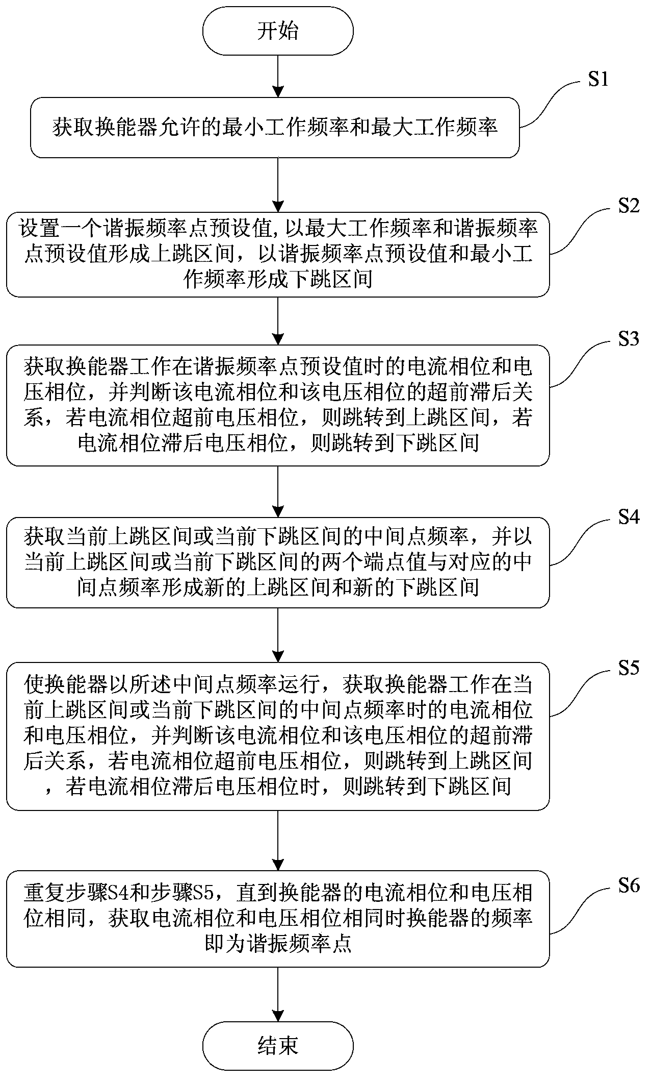
A resonant frequency point and transducer technology, which is applied in the measurement of resonant frequency, frequency measurement device, frequency response correction, etc., can solve the problems of low efficiency, slow speed of finding the resonant frequency point of the transducer, etc. The effect of improving search efficiency and reducing search times

Inactive Publication Date: 2014-11-12
REACH SURGICAL +1
View PDF7 Cites 14 Cited by
  • Summary
  • Abstract
  • Description
  • Claims
  • Application Information

AI Technical Summary

Problems solved by technology

[0006] In view of the shortcomings of the prior art described above, the purpose of the present invention is to provide a method and system for finding the resonance frequency point of the transducer, which is used to solve the problem of slow speed and low efficiency in the prior art for finding the resonance frequency point of the transducer. question

Method used


Image

  • Method and system for searching for resonant frequency point of transducer
  • Method and system for searching for resonant frequency point of transducer
  • Method and system for searching for resonant frequency point of transducer

Examples


Embodiment Construction

[0042] Embodiments of the present invention are described below through specific examples, and those skilled in the art can easily understand other advantages and effects of the present invention from the content disclosed in this specification. The present invention can also be implemented or applied through other different specific implementation modes, and various modifications or changes can be made to the details in this specification based on different viewpoints and applications without departing from the spirit of the present invention.

[0043] At present, the existing way to find the resonant frequency point of the transducer is a frequency sweep method, that is, linearly increasing and decreasing the frequency output energy signal to find the resonant frequency point. The disadvantage is that the search speed is slow and the efficiency is not high. For example, from 50KHz to 60KHz, in order to ensure the accuracy of the search results, it may take 10,000 times of jud...


PUM


Abstract

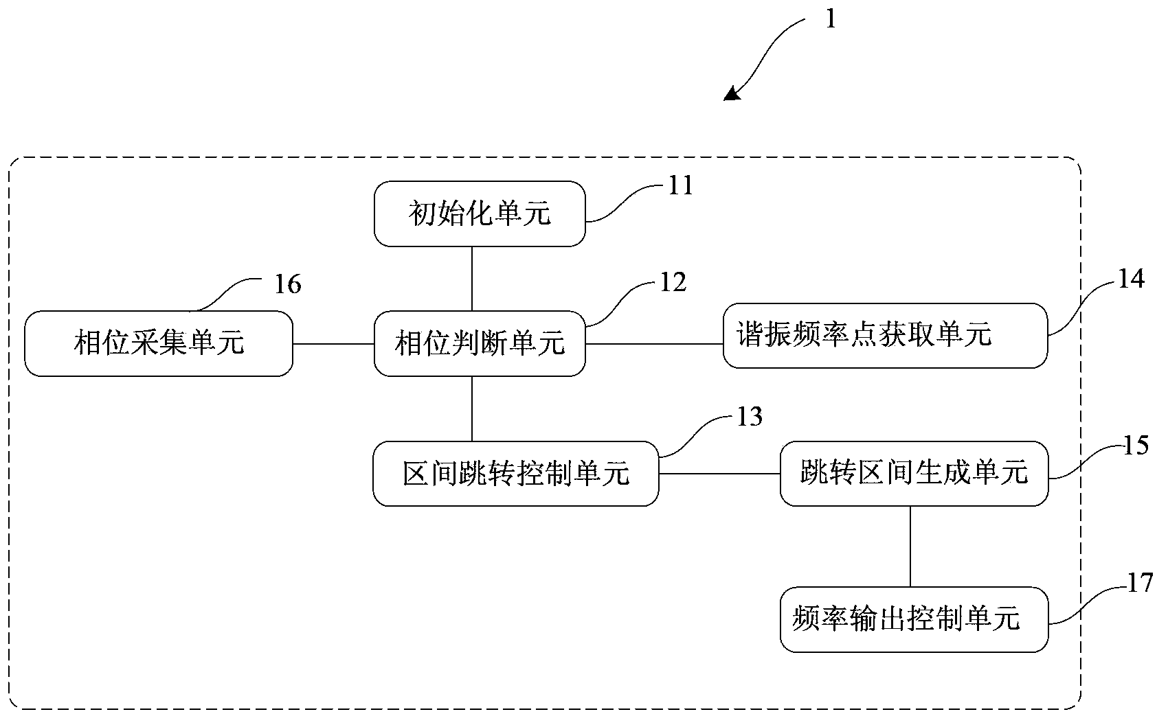
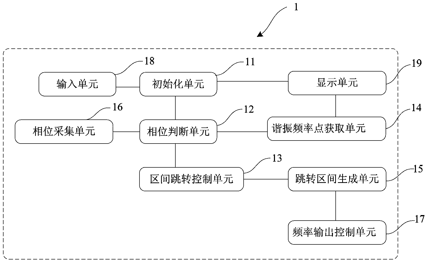
A system for finding a transducer resonant frequency, comprising: an initialization unit (11), a phase determination unit (12), an interval hopping control unit (13), a hopping interval generation unit (15), a frequency output control unit (17), a phase collection unit (16), and a resonant frequency point acquisition unit (14). Each hop allows a search range to be reduced by at least half of that of the previous interval, thus allowing for reduced amount of searches.

Description

technical field [0001] The invention relates to the technical field of transducers, in particular to a method and system for finding a resonance frequency point of a transducer. Background technique [0002] A typical ultrasonic transducer has a high quality factor and a steep resonance curve. Only when it works at its resonance frequency point can it have a large mechanical amplitude and high motor conversion efficiency. Therefore, the driving circuit of the ultrasonic transducer should be excited with its resonant frequency signal. [0003] After the equipment resonates, the operating frequency becomes larger and smaller within a certain range. Since the frequency range is determined by the line in advance, in this way, the operating frequency deviates from the real resonance point in most of the time period, not in the resonance When working at a certain point, it often results in waste of power consumption and reduced efficiency. [0004] In order to obtain the resonan...

Claims


Application Information

Patent Timeline
Patent Type & Authority Applications(China)
IPC IPC(8): G01R23/12
CPCG01H13/00H04R3/04H04R29/001B06B2201/54G01H11/06B06B2201/55H10N30/20
Inventor 张亚东陈启章姚银峰方云才汪炬
Owner REACH SURGICAL
Learn More