Spring mattress

A technology of mattresses and spring components, which is applied in the direction of spring mattresses, mattresses, and stuffed mattresses, etc. It can solve the problems of easy breakage of support springs, poor user feeling, and weak comfort, so as to ensure structural stability , Improve comfort, not easy to damage

Active Publication Date: 2014-11-19
聂坤怀
View PDF6 Cites 7 Cited by
  • Summary
  • Abstract
  • Description
  • Claims
  • Application Information

AI Technical Summary

Problems solved by technology

figure 2 for figure 1 The schematic diagram of the lateral force, when the spring assembly is subjected to a lateral force F from right to left, the component force f of the lateral force F acts on parts B, C, D and E. The disadvantages are: ①The lateral force makes the circular springs in the middle row Staggered by horizontal extrusion, this will lead to uneven arrangement of concave springs in each row; ②Single threaded spring is subjected to the same side force, and it is easy to deform after a long time, the fastening force decreases, the spring mattress deforms, and the service life decreases
[0004] In addition, the overall spring mattress formed by the spring assembly and the surrounding frame (upper and lower surrounding frames), supporting spring and clamping piece has the following disadvantages: ①The diameter of the steel wire of the surrounding frame is about 5mm, while the diameter of the round spring 1.9mm, the elasticity of the "community under force" formed by the circular spring and the through spring is stronger than that of the surrounding frame. Under the action of the same force, the deformation of the spring assembly is greater than the deformation of the surrounding frame. Different, but the clamping piece is made of

Method used


Image

  • Spring mattress
  • Spring mattress
  • Spring mattress

Examples


Embodiment Construction

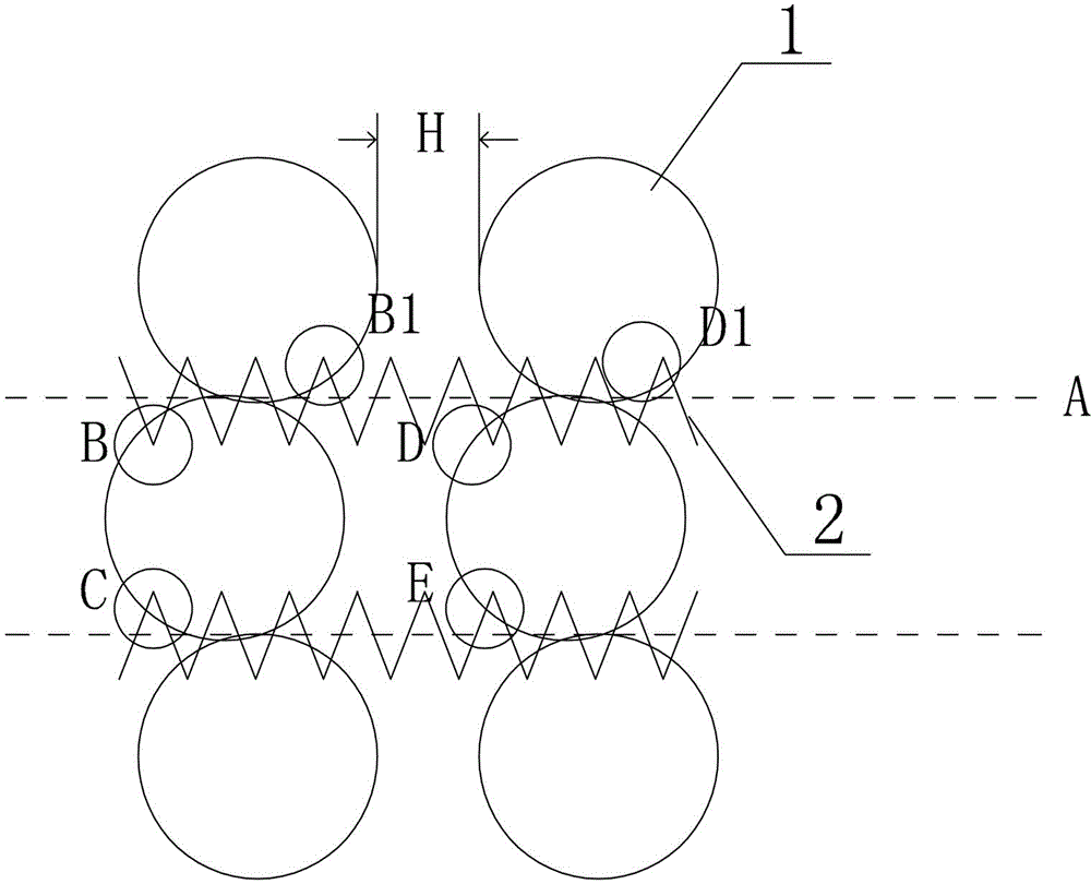
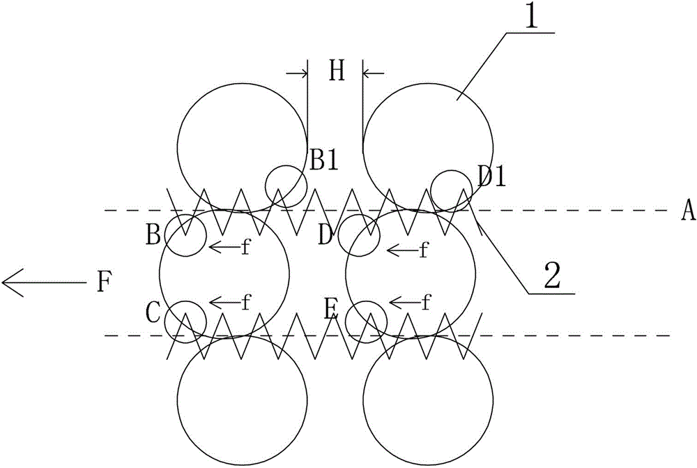
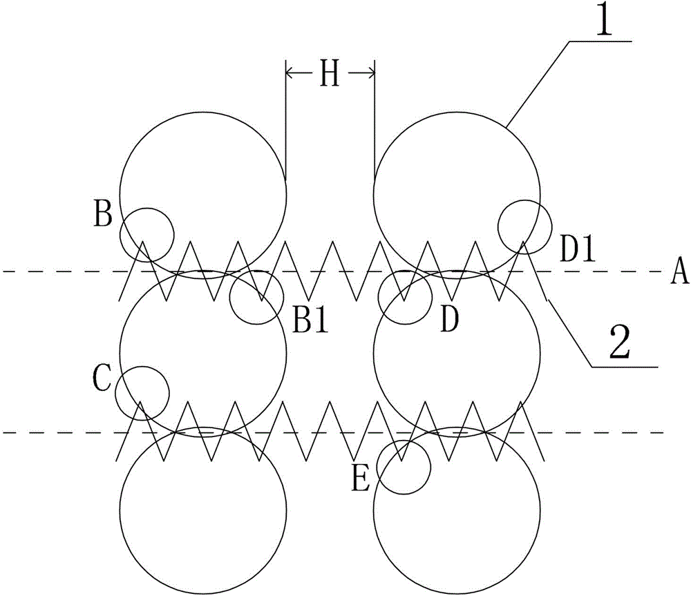
[0017] Such as image 3 , Figure 4 with Figure 5 Shown: a spring mattress, including concave springs 1, springs 2 and filling pads 3, concave springs 1 in a rectangular array, a distance H is left between concave springs 1 in adjacent rows, and concave in adjacent rows The supporting rings of the shaped springs 1 are close to each other or cross, and the through springs 2 are wound on the supporting rings of the concave springs 1 in adjacent rows.

[0018] Among the two adjacent support rings in the same row, the penetration contact part B and the penetration contact part B1 of the support ring of the spring 2 and the concave spring 1 are respectively located on both sides of the thread axis of the spring 2, and so on. Adjacent support rings are also connected with the wear spring 2 in this way.

[0019] In the two adjacent supporting rings in the same row, the penetration contact part B of the wearing spring 22 and the supporting ring of the first concave spring and the ...


PUM

PropertyMeasurementUnit
Diameteraaaaaaaaaa
Diameteraaaaaaaaaa
Free heightaaaaaaaaaa

Abstract

The invention belongs to the technical field of filled mattresses, and discloses a spring mattress. The spring mattress is characterized in that in two adjacent support rings in a same row, a threading spring and a penetrate-in contact portion of two circular spring supporting rings are respectively positioned at two sides of the screw thread axis of the threading spring, the threading spring and a penetrate-out contact portion of the two circular spring supporting rings are respectively positioned at two sides of the screw thread axis, two ends of the threading spring are wound on the corresponding circular spring supporting ring, and circular rings and the threading spring form a spring component. Compared with previously disorganized winding spring mattresses, the spring mattress disclosed in the invention has the advantages of structure firmness and balanced force bearing of a whole spring core, and reduction of the hidden quality trouble possibility caused by the structure of the spring core by researching a winding method through analyzing the force bearing conditions of the supporting rings and the threading spring.

Description

technical field [0001] The invention belongs to the technical field of stuffed mattresses. Background technique [0002] Spring mattress is a bedding made of spring and soft padding as the inner core material, and the outer cover is made of fabric fabric or soft mat. Spring mattresses have a relatively even and reasonable distribution of body support, which can not only play a sufficient supporting role, but also ensure a reasonable physiological curvature of the spine, and has become the mainstream stuffed mattress. [0003] Existing spring mattresses usually consist of an upper frame, a lower frame, a circular spring, a threaded spring, a support spring and a clamping piece. figure 1 It is a top view of the spring assembly formed by the connection of the circular spring and the threaded spring in the existing spring mattress (with the vertical as a column and the horizontal as a row). or the lower support ring) connected in series, in the same horizontally adjacent longi...

Claims


Application Information

Patent Timeline
IPC IPC(8): A47C27/06A47C27/07A47C27/05
Inventor 聂坤怀聂颖聂波
Owner 聂坤怀
Why Eureka
Try Eureka