Cog bonding machine terminal cleaning pressure head mechanism

A technology of bonding machine and pressure head, applied in the direction of cleaning flexible objects, cleaning methods and utensils, workpiece clamping devices, etc., can solve the problems of reducing equipment working efficiency, inability to guarantee product quality, inconvenient adjustment of parallelism, etc., and achieve structural Simple, time-saving, easy-to-adjust effects

Active Publication Date: 2016-06-08
DALIAN YISHENGDA INTELLIGENT TECH
View PDF8 Cites 0 Cited by
  • Summary
  • Abstract
  • Description
  • Claims
  • Application Information

AI Technical Summary

Problems solved by technology

[0002] With the continuous innovation of technology, the degree of automation of equipment is getting higher and higher. The cleaning mechanism of COG bonding machine under the existing technology is connected by ordinary screws, which is inconvenient to adjust parallelism, which will waste a lot of adjustment time and reduce the equipment efficiency
Can not guarantee product quality

Method used


Image

  • Cog bonding machine terminal cleaning pressure head mechanism

Examples


Embodiment Construction

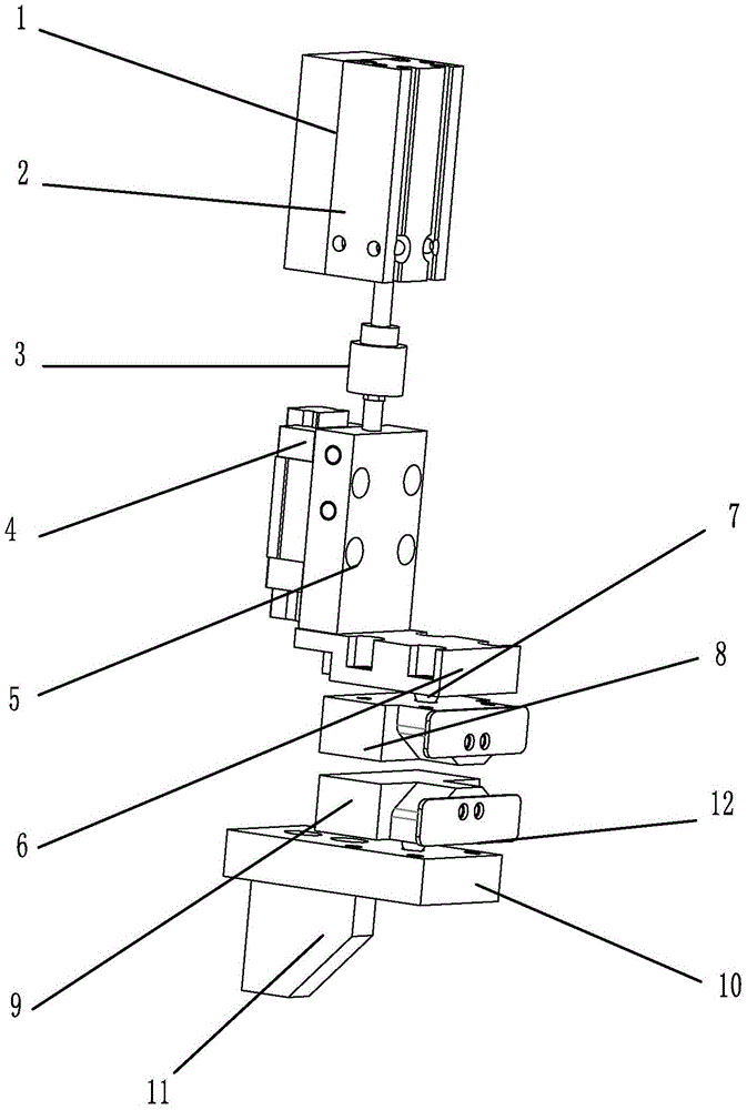
[0008] The connection process of the device of the present invention, such as figure 1 The shown cylinder 2 is fixed on the top of the machine tool body plate 1, the floating joint 3 is connected to the bottom of the cylinder, the middle plate 5 under the floating joint 3, the guide rail slider 4 is installed under the middle plate 5, and the connecting plate 6 is fixed on the bottom surface of the middle plate 5 , The connecting plate 6 is connected to the pressure head 8 by bolts, and a steel ball 7 is installed between the two parts, so that the upper part of the pressure head is assembled. The lower part first fixes the supporting plate 10 on the rib plate 11 of the machine tool body, the supporting plate 10 is connected with the back supporting plate 9 through bolts, and a steel ball 7 is installed between the back supporting plate 9 and the supporting plate 10, and the pressure head and the back supporting plate Guide piece 12 is housed respectively on the plate, and who...


PUM


Abstract

A pressure head mechanism for terminal cleaning of COG (chip on glass) binding machine comprises an upper pressure head 8 and a lower back-up plate 9. During operation, glass to be cleaned is pressed in the middle of the upper pressure head 8 and the lower back-up plate 9 during operation which are respectively fixedly connected to an upper pressurizing and driving unit and a lower fixing and supporting unit in a bolt binding manner, and steel balls 7 are respectively nested between the upper pressure head 8 and the upper pressurizing and driving unit as well as between the back-up plate 9 and the top supporting part of the supporting unit. The pressure head can be adjusted by the aid of rotation of the steel balls, so that the pressure head mechanism has the advantages of simple structure, convenience in adjustment, saved time, high efficiency and the like; through simple adjustment, the pressure head and the back-up plate can be guaranteed to be in a parallel state, and damage to the glass can be prevented on the premise that the cleaned glass is positioned.

Description

technical field [0001] The present invention relates to a COG bonding machine, more specifically, relates to a pressure head mechanism used for fixing the glass when the terminal of the bonding machine is cleaning the glass. Background technique [0002] With the continuous innovation of technology, the degree of automation of equipment is getting higher and higher. The cleaning mechanism of COG bonding machine under the existing technology is connected by ordinary screws, which is inconvenient to adjust parallelism, which will waste a lot of adjustment time and reduce the equipment efficiency. Product quality cannot be guaranteed. In particular, when the mechanism is working, the pressure head and the back plate must be in a parallel state, otherwise the glass is prone to defective products. Contents of the invention [0003] The invention utilizes the rotation of the steel ball to realize the adjustment of the pressure head, which has the advantages of simple structure...

Claims


Application Information

Patent Timeline
Patent Type & Authority Patents(China)
IPC IPC(8): B08B11/04B08B13/00
CPCB08B11/04B08B13/00B25B11/00
Inventor 李忠奎邹艳秋
Owner DALIAN YISHENGDA INTELLIGENT TECH
Why Eureka
Try Eureka