Method for flexible design of spiral groove skew rolling roller

A design method and technology of spiral holes, applied in the direction of rolls, metal rolling, metal rolling, etc., can solve the problems of reduced design accuracy, complicated design process, cumbersome and complicated, etc., to avoid errors, accurate three-dimensional design, and ensure design accuracy Effect

Active Publication Date: 2014-11-19
WUHAN UNIV OF TECH
View PDF6 Cites 4 Cited by
  • Summary
  • Abstract
  • Description
  • Claims
  • Application Information

AI Technical Summary

Problems solved by technology

However, due to the complex surface of the roll die pass, which is a spiral pass with variable lead and variable height, there is no efficient and accurate design method at present.
The traditional design is to use programming to calculate the data points of the characteristic curve on the pass surface, and then import them into the 3D software to fit each characteristic curve and surface in turn, and finally materialize the roll surface. This process is cumbersome and complicated. Reduced design accuracy
In addition, when designing rolls of different sizes and specifications, or needing to adjust and correct the structural parameters of the roll pass, the traditional method has to be re-started one by one, which consumes a lot of design time and effort
Therefore, the existing spiral pass cross rolling roll design process is complicated, low in efficiency, and poor in precision, which does not conform to the modern design concept, nor can it better meet the design requirements of the spiral pass cross rolling process.

Method used

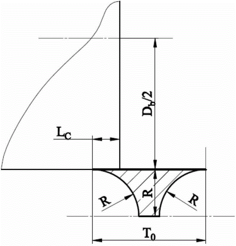
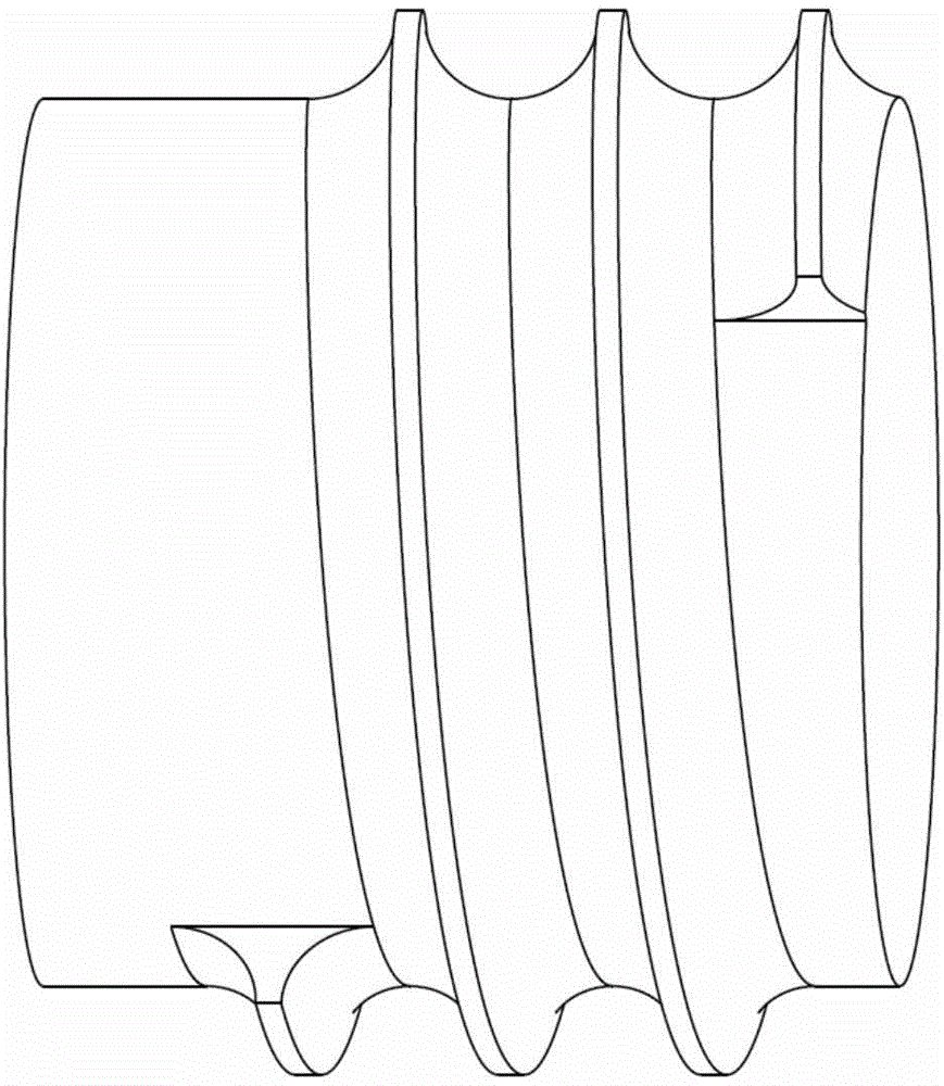
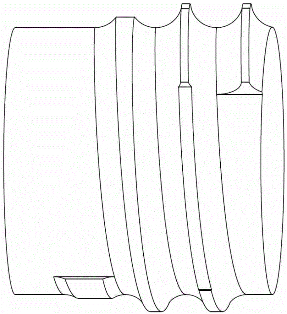

Image

  • Method for flexible design of spiral groove skew rolling roller
  • Method for flexible design of spiral groove skew rolling roller
  • Method for flexible design of spiral groove skew rolling roller

Examples


example 1

[0074] In the following, the establishment and reliability of the parameter model of the roll for cross-rolling of spherical parts will be discussed by taking the roll for cross-rolling of bearing steel balls with a radius R of 15 mm as an example.

[0075] 1) According to the cross-rolling process design method, calculate the parameters of the roll pass for the cross-rolling forming of bearing steel balls with a radius R of 15mm, and input each parameter into the parameter list of the parametric model as shown below (the unit of length is mm , angles are in degrees).

[0076]

[0077]

[0078] 2) Take the base circle of the roll as the cross-section profile, and create a cylindrical solid feature through the stretch command. The cross-sectional circular size is determined by the diameter D in the parameter list b = 150mm driving to get.

[0079] 3) Create the initial rib helical trajectory and profile section, and create the initial helical rib on the solid cylindrica...


PUM


Abstract

The invention belongs to the field of rotation plastic processing and discloses a method for flexible design of a spiral groove skew rolling roller. The method is characterized by comprising the steps of firstly, setting and defining relevant parameters of a roller groove in 3D modeling software; secondly, establishing a cylinder solid feature through a stretching command with the base circle of the roller serving as the cross section outline; thirdly, establishing an initial flange spiral trajectory and an outline cross section, and establishing an initial spiral flange on the solid cylindrical surface with the screw pitch serving as the basic lead and the height serving as the radius of the portion, with the largest cross section, of a rolled piece by scanning the initial flange outline cross section along the spiral trajectory; fourthly, obtaining flange heights at different groove positions and achieving the purpose that the height of the flange of the roller changes according to a designed change rule; fifthly, achieving the variable-lead geometrical transformation feature of the spiral groove of the roller; sixthly, finishing all the three-dimensional design of the skew rolling roller. By the adoption of the method, a 3D solid model of the roller can be generated quickly and accurately, flexible design of the roller is achieved, and design efficiency and accuracy are improved remarkably.

Description

technical field [0001] The invention belongs to the field of rotary plastic processing, and in particular relates to a flexible design method for spiral pass skew rolling rolls of spherical, cylindrical or conical rotary parts. Background technique [0002] Spiral pass cross rolling (referred to as cross rolling) is an advanced rotary plastic forming technology for spherical, cylindrical, conical and other rotary parts. Compared with traditional forging, casting and turning processes, it has high quality, energy saving, material saving and high efficiency. It is widely used in the forming and manufacturing of rotating parts such as ball milling steel balls, bearing steel balls and rollers. In spiral pass cross rolling, accurate roll design is an important guarantee for roll manufacturing and precision of rolled products. However, due to the complex surface of the roll die pass, which is a helical pass with variable lead and variable height, there is no efficient and accurat...

Claims


Application Information

Patent Timeline
Patent Type & Authority Applications(China)
IPC IPC(8): B21B27/02
Inventor 钱东升华林曹强
Owner WUHAN UNIV OF TECH
Why Eureka
Try Eureka