
Valve boring lathe tool

A technology of machine tool and boring car, which is applied in the field of processing the outer circle of the flange surface, can solve the problems of insecurity, error, time-consuming and labor-intensive, etc., and achieve the effect of small error, high precision and high efficiency.

Inactive Publication Date: 2014-11-19
SHENYANG NORTH SPECIAL MACHINE TOOL DESIGN INST
View PDF7 Cites 8 Cited by
  • Summary
  • Abstract
  • Description
  • Claims
  • Application Information

AI Technical Summary

Problems solved by technology

[0005] First, when using a lathe to process the outer circle of the flange, because the valve is not round as a whole, and the turning tool fixes the valve to rotate, it causes a large eccentricity. The card is not at one end and the distance is far away, it is easy to fail to install the card, which is not safe
[0006] Second, today's machine tools need to be installed and disassembled separately when processing multiple flanges on a valve, that is, each time a flange is processed, it needs to be assembled and disassembled once, which is time-consuming and laborious, and manual loading and unloading makes the gap between the flange surface and the tool A position deviation occurs, resulting in an error
[0007] Third, the existing tools can only process the outer circle of a single flange surface

Method used


Image

  • Valve boring lathe tool
  • Valve boring lathe tool
  • Valve boring lathe tool

Examples


Embodiment Construction

[0049] The following describes the present invention in detail, and the features and advantages of the present invention will become more clear and definite along with these descriptions.

[0050] The word "exemplary" is used exclusively herein to mean "serving as an example, embodiment, or illustration." Any embodiment described herein as "exemplary" is not necessarily to be construed as superior or better than other embodiments. While various aspects of the embodiments are shown in drawings, the drawings are not necessarily drawn to scale unless specifically indicated.

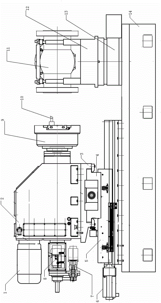
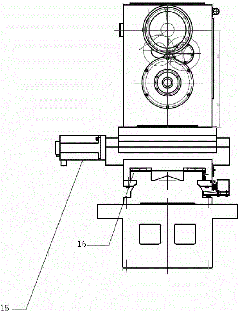
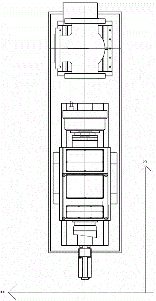
[0051] In a preferred embodiment of the present invention, such as Figure 1-3 As shown in , a valve boring machine tool is provided, which includes:

[0052] The machine tool base 14 is fixedly equipped with a CNC four-station turntable 13 on the upper right side, the left side of the machine tool base 14 is provided with a longitudinal slide rail along its longitudinal direction, and the left edge of the...


PUM


Abstract

The invention discloses a valve boring lathe tool which comprises a tool base, a numerical control four-station rotating table, a longitudinal sliding rail, a Z-axis servo motor, a sliding saddle, a transverse sliding rail, an X-axis servo motor, a sliding plate, a boring power head, a boring cutter head, a main motor, a boring cutter drive mechanism, a boring cutter servo motor and a boring cutter. The valve boring lathe tool has the advantages of being high in precision, small in error, high in efficiency and the like; by means of the four-station rotating table, an outer circle of a flange plate with a plurality of flange faces can be machined at a time, and a plurality of flange faces, a boss, a water line and the outer circle can be machined by means of the boring cutter drive mechanism.

Description

technical field [0001] The invention relates to the processing technology of the outer circle of the flange face, in particular to a valve boring machine tool for simultaneously processing three flange faces. Background technique [0002] Valves are essential fluid control components in various industrial and economic industries such as petroleum, chemical industry, long-distance pipelines and electric power. There are many types of valves, and the valves are equipped with end flanges and middle flanges. [0003] Flange is also called flange or flange. Flanges are parts that connect pipes and pipes and valves to each other, and are connected to the pipe end. There are holes in the flange, and the bolts tightly connect the two flanges. The flanges are sealed with gaskets. Flanges are divided into threaded (wire) flanges, welding flanges and ferrule flanges. [0004] The outer circle of the flange, the flange surface, the boss, and the waterline all need to be processed, a...

Claims


Application Information

Patent Timeline
IPC IPC(8): B23B41/00B23B47/06B23B47/20B23Q1/25
CPCB23B43/00B23Q1/25B23Q5/36B23Q5/402
Inventor 郑先道闫洪奎刘丽凤
Owner SHENYANG NORTH SPECIAL MACHINE TOOL DESIGN INST
Learn More