A dual-interface smart card chip welding method and welding equipment

A double-interface smart card and chip welding technology, applied in welding equipment, welding equipment, auxiliary welding equipment, etc., can solve the problems of affecting welding, affecting welding quality, card scrapping, etc., so as to facilitate dissipation and heat dissipation, improve welding quality, and improve The effect of product quality

Active Publication Date: 2015-09-30
GUANGZHOU MINGSEN TECH CO LTD
View PDF9 Cites 0 Cited by
  • Summary
  • Abstract
  • Description
  • Claims
  • Application Information

AI Technical Summary

Problems solved by technology

[0005] 1.1. When the clamping jaws are clamping the wire, the two clamping jaws move from both sides to the middle to clamp the antenna. When the antenna touches the clamping jaws, the surface of the clamping jaws will stick the antenna, so that the antenna cannot be straightened freely, resulting in bending Fold shape, affect welding;
[0006] 1.2. The adhered soot and dirt will reduce the heat transfer speed of the welding joint, affecting the production efficiency and the welding quality of the card;
[0007] 1.3. When it is found that cleaning is required, some cards have problems in welding, which makes this part of the cards scrapped
[0008] 2. Due to the antenna clamping device clamping the antenna during welding, the oil fume generated during welding cannot be dissipated in time, so that the welding part cannot be cooled quickly, which affects the welding quality
The time taken by the antenna clamping action will affect the overall production capacity

Method used


Image

  • A dual-interface smart card chip welding method and welding equipment
  • A dual-interface smart card chip welding method and welding equipment
  • A dual-interface smart card chip welding method and welding equipment

Examples


Embodiment 1

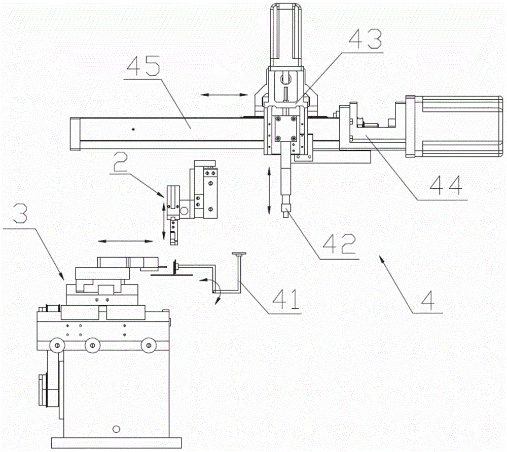
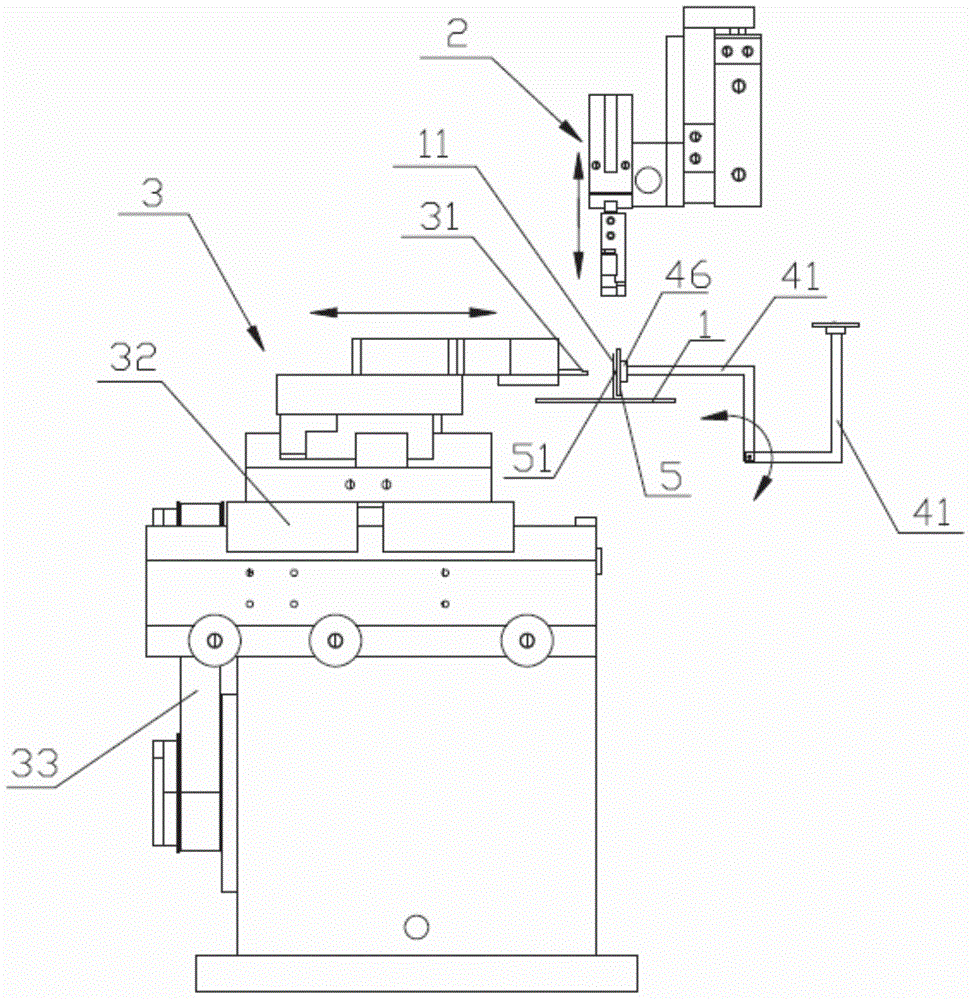
[0045] see Figure 1 to Figure 9 , the smart card chip 5 welding method of present embodiment 1 comprises the following steps:

[0046] (1) Transport the card 1 that has been picked up by the antenna 11 to the welding station, and then the antenna slapping device 2 moves to the station to slap the two antennas 11 so that the two antennas 11 are located on the vertical plane, And the distance between the two antennas 11 is equal to the distance between the centers of the two solder joints 51 on the chip 5. After the beating is completed, the antenna line shooting device 2 leaves the welding station;

[0047] Specifically, the antenna line shooting device 2 moves from top to bottom to the welding station, and after the line shooting is completed, the antenna line shooting device 2 moves upward to reset;

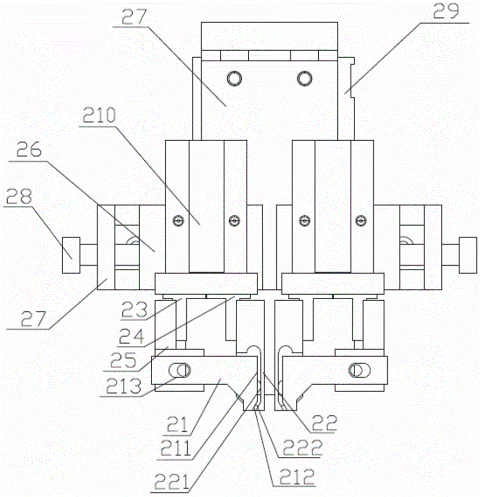
[0048] Further, see Figure 6 ~ Figure 9 , the line shooting action of the antenna shooting line device 2 is realized by two pairs of claws, and both pairs of claws can be cl...

Embodiment 2

[0060] In Example 1, since the wire surface of the claw is located on the vertical plane, after the wire is completed, the antenna may be shifted to the outside by a certain distance, so that it cannot be completely vertical, thereby offsetting the solder joint. May affect welding quality. The reason is: see Figure 10 ~ Figure 12 , before performing the wire shooting process of the present invention, the card 1 needs to go through the following processing process: first, the chip groove 12 is milled out on the card 1 corresponding to the two antennas 11, so that the antenna 11 hidden in the card 1 is exposed , when milling the chip slot 12, when the antenna 11 is exposed, it is necessary to bend the two antennas 11 to both sides of the chip slot 12 (equivalent to reverse bending the antenna 11 along its extending direction in the card), Make it close to the state of lying flat on the card surface, so as not to cut off the antenna 11 when milling the groove; then it is necess...


PUM


Abstract

The invention discloses a double-interface smart card chip welding method and device. The double-interface smart card chip welding method includes steps of (1) conveying cards lifted up by two antennas to a welding workstation, then moving an antenna beating device to the workstation to beat the antennas so that the antennas are arranged on the same plumb surface, and after beating, removing the antenna beating device from the welding workstation, wherein the distance between the antenna is equal to that between the centers of two welding points on a chip; (2) conveying the chip to be welded to the welding workstation by a chip conveying device 2 and guaranteeing that the chip is vertically arranged and the two welding points on the chip are flush with the antennas; (3) enabling a welding head of the welding device to move towards the welding points and the antennas and welding the antennas on the welding points. During welding by the welding method, the antennas do not have to be continuously clamped, cleaning jaws are not needed to be cleaned, and the double-interface smart card chip welding method and device have the advantages high welding efficiency and quality and the like.

Description

technical field [0001] The invention relates to production equipment and a method of a dual-interface smart card, in particular to a dual-interface smart card chip welding method and welding equipment. Background technique [0002] In the production process of the dual-interface smart card, the chip needs to be soldered to the antenna of the card, and then the chip is packaged. In the existing chip soldering process, when the chip is soldered, it is necessary to lift the two antennas into a vertical state first, and then clamp the antennas through the antenna clamping mechanism. The purpose of clamping is to ensure the position of the two antenna ends. Make corrections to ensure that the distance between the ends of the two antennas is equal to the distance between the solder points on the chip, then move the chip to be soldered close to the antenna, and align the two solder points on the chip with the ends of the two antennas , and finally the welding head of the welding m...

Claims


Application Information

Patent Timeline
Patent Type & Authority Patents(China)
IPC IPC(8): B23K37/00
CPCB23K31/02B23K37/00
Inventor 王开来吴伟文房训军赖汉进黄文豪陈伟
Owner GUANGZHOU MINGSEN TECH CO LTD
Why Eureka
Try Eureka