Precise numerical-control spindle system

A precise numerical control and rotating shaft technology, applied in control systems, motor control, and mechanical energy control, etc., can solve problems such as expensive, difficult to meet precise positioning, unable to achieve 360-degree rotation positioning, etc., to avoid dead point problems and simple structure. Effect

Active Publication Date: 2014-11-19
SHENZHEN LLMACHINECO LTD
View PDF6 Cites 5 Cited by
  • Summary
  • Abstract
  • Description
  • Claims
  • Application Information

AI Technical Summary

Problems solved by technology

Since the reducer is usually composed of several sets of gears that cooperate with each other, and the gear mechanism is a high-motion pair, the matching tolerance is generally relatively large, and it is difficult to meet the needs of precise positioning.
[0004] Moreover, the high-precision and low-clearance reducers on the market are often expensive and are not suitable for large-scale promotion in industrial sites.
[0005] Using a crank slider mechanism to control the rotation of the output shaft will have a dead point, which cannot achieve 360-degree rotation positioning

Method used


Image

  • Precise numerical-control spindle system
  • Precise numerical-control spindle system
  • Precise numerical-control spindle system

Examples


Embodiment Construction

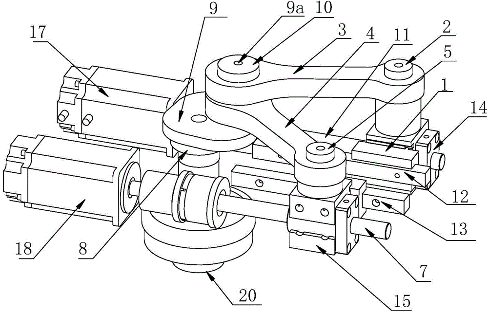
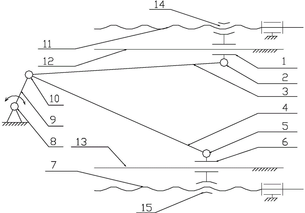
[0020] The structure of the precision numerical control rotating shaft system in the embodiment of the present invention is as follows: figure 1 shown, including the rack ( figure 1 Not shown in), output shaft 20, controller (not shown) and drive system, the drive system includes two sets of drive devices, each set of drive devices includes a set of slider crank mechanism and a set of screw nut mechanism. With respect to the rotation angle of the output shaft 20, the dead points of the two sets of crank-slider mechanisms are staggered from each other.

[0021] Two sets of slider crank mechanisms share the same crank 9 and the same crank pin 9a. Crank 9 is fixed on the upper end of output shaft 20, and rotating output shaft 20 is installed on the frame by main bearing 8, and output shaft 20 is driven by crank 9 and rotates synchronously by the constraint of main bearing 8.

[0022] The first set of slider crank mechanism comprises connecting rod 3, connecting rod slider beari...


PUM


Abstract

The invention discloses a precise numerical-control spindle system. The precise numerical-control spindle system comprises a frame, an output shaft and a driving system, wherein the output shaft is rotationally mounted on the frame through a main bearing, and the driving system comprises two driving devices. Each driving device comprises a crank slider mechanism and a screw nut mechanism. Guide rails of sliders of the crank slider mechanisms are fixed on the frame, cranks are fixed with the hinged end of the frame and the output shaft, and dead points of the crank slider mechanisms are mutually staggered relative to rotation angle of the output shaft; screws of the screw nut mechanisms are mounted on the frame through screw bearings, nuts are connected with the sliders of the crank slider mechanism, the screws of the driving devices rotate together, the nuts drive the sliders to translate, and the cranks of the crank slider mechanisms jointly drive the output shaft to rotate. The driving devices together drive the output shaft to rotate, possible dead points of one crank slider mechanism can be effectively avoided, and 360-degree rotation and positioning can be realized.

Description

[technical field] [0001] The invention relates to a precision positioning system, in particular to a precision numerical control rotating shaft system. [Background technique] [0002] In the application of rotary motion control, although the combination of the drive motor directly connected to the actuator has the characteristics of small clearance and high repeatability, its disadvantages are also obvious, that is, due to the technical limitations of the drive motor, the drive motor used for positioning The output torque is often relatively low, which is difficult to meet actual needs. [0003] In the various combinations of the motor and the actuator, it is generally connected with a reducer with various reduction ratios, and the output torque is increased through the reducer to meet actual needs. Since the reducer is usually composed of several sets of gears that cooperate with each other, and the gear mechanism is a high-speed pair of motion, the matching tolerance is g...

Claims


Application Information

Patent Timeline
Patent Type & Authority Applications(China)
IPC IPC(8): B23Q5/10
CPCF16H37/124H02K7/10H02P29/00
Inventor 谭军谢胤
Owner SHENZHEN LLMACHINECO LTD
Why Eureka
Try Eureka