
Megawatt wind power generation blade with blade-tip turbulent flow structure and forming method of megawatt wind turbine blade

A technology of wind power generator and forming method, which is applied in the direction of wind power generator components, wind power engines, wind power generation, etc., which can solve the problems of blade stability decline, wake effect enhancement, blade aerodynamic performance degradation, etc., and achieve the suppression of blade tip vortex The effect of generating, improving running stability, and improving aerodynamic performance

Active Publication Date: 2014-11-19
SINOMATECH WIND POWER BLADE +1
View PDF5 Cites 8 Cited by
  • Summary
  • Abstract
  • Description
  • Claims
  • Application Information

AI Technical Summary

Problems solved by technology

[0002] Generally, the blades of megawatt-class wind turbines often generate large induced resistance at the blade tip when they rotate, which reduces the aerodynamic performance of the blade, and the blade tip vortex formed near the blade tip will lead to the stability of the blade during operation. descending, the wake effect is enhanced, and greater aerodynamic noise is generated
[0003] Many wind turbine blade research institutions and manufacturers are committed to improving the shape of the blade to reduce the induced resistance and improve the aerodynamic efficiency of the blade, such as using a symmetrical airfoil at the blade tip to reduce the lift of the blade tip; but the chord at the blade tip The length is small, the adjustable space is limited, and the effect is not ideal
[0004] So far, there is no report on the successful improvement of megawatt wind turbine blades that can reduce the induced drag and improve the aerodynamic efficiency of the blades

Method used


Image

  • Megawatt wind power generation blade with blade-tip turbulent flow structure and forming method of megawatt wind turbine blade
  • Megawatt wind power generation blade with blade-tip turbulent flow structure and forming method of megawatt wind turbine blade
  • Megawatt wind power generation blade with blade-tip turbulent flow structure and forming method of megawatt wind turbine blade

Examples


Embodiment Construction

[0040] In the 1970s, R.T. Whitcomb of the National Aeronautics and Space Administration (NASA) Ames Research Center invented the winglet (Winglet, Whitcomb R T.A design approach and selected wind-tunnel results at high subsonic speeds for wing-tip mounted winglets.NASA TND-8260,1976), its function is to reduce the induced drag of the wing and weaken the wake of large aircraft to reduce the impact of aircraft wake on the airspace of the airport through the winglet.

[0041] The blade tip turbulence structure designed by the present invention is based on the same principle of the winglet of the aircraft. The design of the winglet of the aircraft is suitable for the subsonic low-speed flow of 0.6-0.8Ma, while the present invention is aimed at the low-speed flow below 0.3Ma. , by installing a spoiler structure near the tip, the spoiler area of ​​the tip is increased to form a flow opposite to the tip vortex to reduce the induced resistance, improve the aerodynamic performance of th...


PUM

PropertyMeasurementUnit
Widthaaaaaaaaaa

Abstract

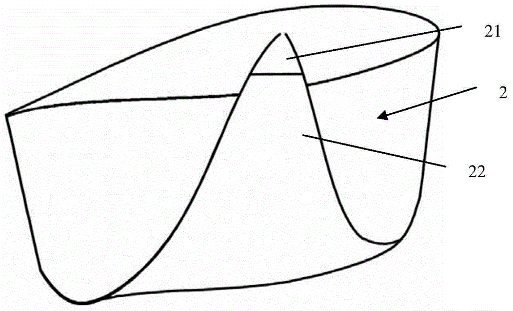
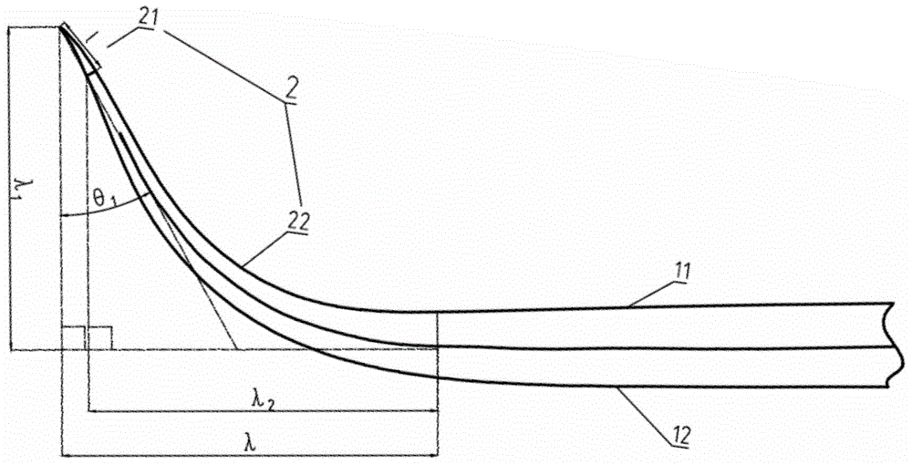
The invention discloses a megawatt wind power generation blade with a blade-tip turbulent flow structure. The root of the blade is connected with a wind power generator, the leeward of the blade is a suction surface while the windward side is a pressure surface, the turbulent flow structure formed by a lightening-protection flash receiving point and a fusion transition portion and used for improving pneumatic performance of a blade tip is arranged at the position close to one end of the blade, the fusion transition portion bends to the position of the suction surface, and the lightening-protection flash receiving point is fixed on the suction surface of the fusion transition portion. The blade-tip turbulent flow structure is designed by the application of the bionics concept and reference of large birds such as eagles gliding and flying to have feathers at the positions of wing tips bend upwards as well as successful application of winglets at aircraft wingtips which is used for reference, induced resistance can be effectively decreased, blade tip turbulence can be restrained, pneumatic noise of the blade can be effectively controlled, and pneumatic performance of the blade can be improved.

Description

technical field [0001] The invention relates to a blade of a megawatt-level wind power generator, in particular to a blade of a megawatt-level wind power generator with a tip spoiler structure and a forming method thereof. Background technique [0002] Generally, the blades of megawatt-class wind turbines often generate large induced resistance at the blade tip when they rotate, which reduces the aerodynamic performance of the blade, and the blade tip vortex formed near the blade tip will lead to the stability of the blade during operation. When descending, the wake effect is enhanced, and larger aerodynamic noise is generated. [0003] Many wind turbine blade research institutions and manufacturers are committed to improving the shape of the blade to reduce the induced resistance and improve the aerodynamic efficiency of the blade, such as using a symmetrical airfoil at the blade tip to reduce the lift of the blade tip; but the chord at the blade tip The length is small, t...

Claims


Application Information

Patent Timeline
IPC IPC(8): F03D11/00
CPCF03D80/30Y02E10/72
Inventor 乔玉军李成良陈淳王向东丁惢
Owner SINOMATECH WIND POWER BLADE
Learn More