Compressor roller, compressor pump body and compressor

A compressor pump, compressor technology, applied in the direction of machine/engine, pump components, mechanical equipment, etc., can solve the problem that the eccentricity of the crankshaft 5 cannot reach the theoretical maximum value, the maximum displacement is small, etc.

Active Publication Date: 2014-11-19
郑州凌达压缩机有限公司
View PDF6 Cites 2 Cited by
  • Summary
  • Abstract
  • Description
  • Claims
  • Application Information

AI Technical Summary

Problems solved by technology

[0005] According to the above content, it can be known that due to the restriction of the minimum length of the sealing belt L1 between the inner diameter of the roller 4 and the exhaust hole 1, the eccentricity of th

Method used


Image

  • Compressor roller, compressor pump body and compressor
  • Compressor roller, compressor pump body and compressor
  • Compressor roller, compressor pump body and compressor

Examples


Embodiment Construction

[0029] The embodiments of the present invention will be described in detail below with reference to the accompanying drawings, but the present invention can be implemented in many different ways defined and covered by the claims.

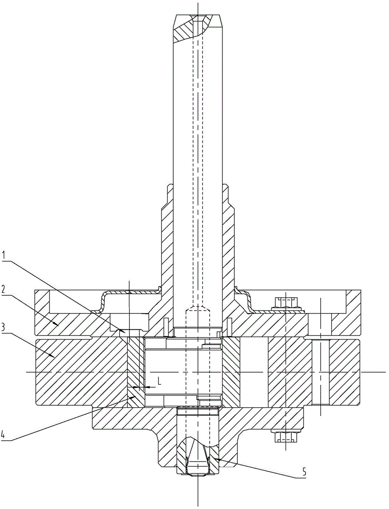
[0030] see Figure 4 and Figure 9 As shown, according to the first implementation of the compressor roller of the present invention, a compressor roller is provided, which includes a cylindrical roller body 10 and a first end of the roller body 10 Inner flange 60. Due to the inner flange 60 of the compressor roller in this embodiment, the setting of the inner flange 60 can meet the sealing requirements of the compression cylinder 30, form a longer sealing band, and avoid the leakage phenomenon of the compression cylinder 30. At the same time, due to The compressor rollers already have an inner flange 60 to prevent compressor leakage. At the same time, the sealing zone of the compressor with the largest displacement using the original roller struc...


PUM


Abstract

The invention provides a compressor roller, a compressor pump body and a compressor. The compressor roller comprises a cylindrical roller main body, and an inner flange arranged at a first end of the roller main body. Under the condition of satisfying the sealing requirement of a compression cylinder, the displacement of the compressor can be increased, so that the displacement of the compressor reaches the highest theoretical displacement.

Description

technical field [0001] The invention relates to the technical field of air conditioning, and more specifically, to a compressor roller, a compressor pump body and a compressor. Background technique [0002] see figure 1 As shown, in the existing two-cylinder compressor with single cylinder and single exhaust and the exhaust structure is the upper and lower flange exhaust, considering the generalization of the use of parts, compressors using the same compression cylinder 3 with different displacements will use the same Upper flange 2. At the same time, considering the smoothness and resistance of the exhaust, the upper flange 2 is provided with an exhaust hole 1, and the distance between the exhaust hole 1 and the center line of the upper flange 2 will not be too far or too close. The same goes for size. [0003] For details, see figure 2 and image 3 shown in figure 2 Among them, d1 is the inner diameter of the compression cylinder 3, d2 is the diameter of the roller...

Claims


Application Information

Patent Timeline
IPC IPC(8): F04C29/00
Inventor 李雄辉
Owner 郑州凌达压缩机有限公司
Why Eureka
Try Eureka