Rotary splashing device

A splashing device and water splashing technology, applied in water shower coolers, direct contact heat exchangers, heat exchanger types, etc., can solve the problem of poor uniformity of circumferential water distribution, and achieve uniform, moderate size, The effect of eliminating the hollow phenomenon of water distribution

Inactive Publication Date: 2014-11-19
魏熙臣
View PDF5 Cites 4 Cited by
  • Summary
  • Abstract
  • Description
  • Claims
  • Application Information

AI Technical Summary

Problems solved by technology

[0015] The purpose of the present invention is to provide a spraying water distribution along the radial direction, the bottom of the nozzle is the largest, extending outwards, the water volume gradually decreases with the increase of the distance from the center, and there is no hollow phenomenon, no umbrella-shaped water film, and the splashing radius

Method used


Image

  • Rotary splashing device
  • Rotary splashing device
  • Rotary splashing device

Examples


specific Embodiment approach 1

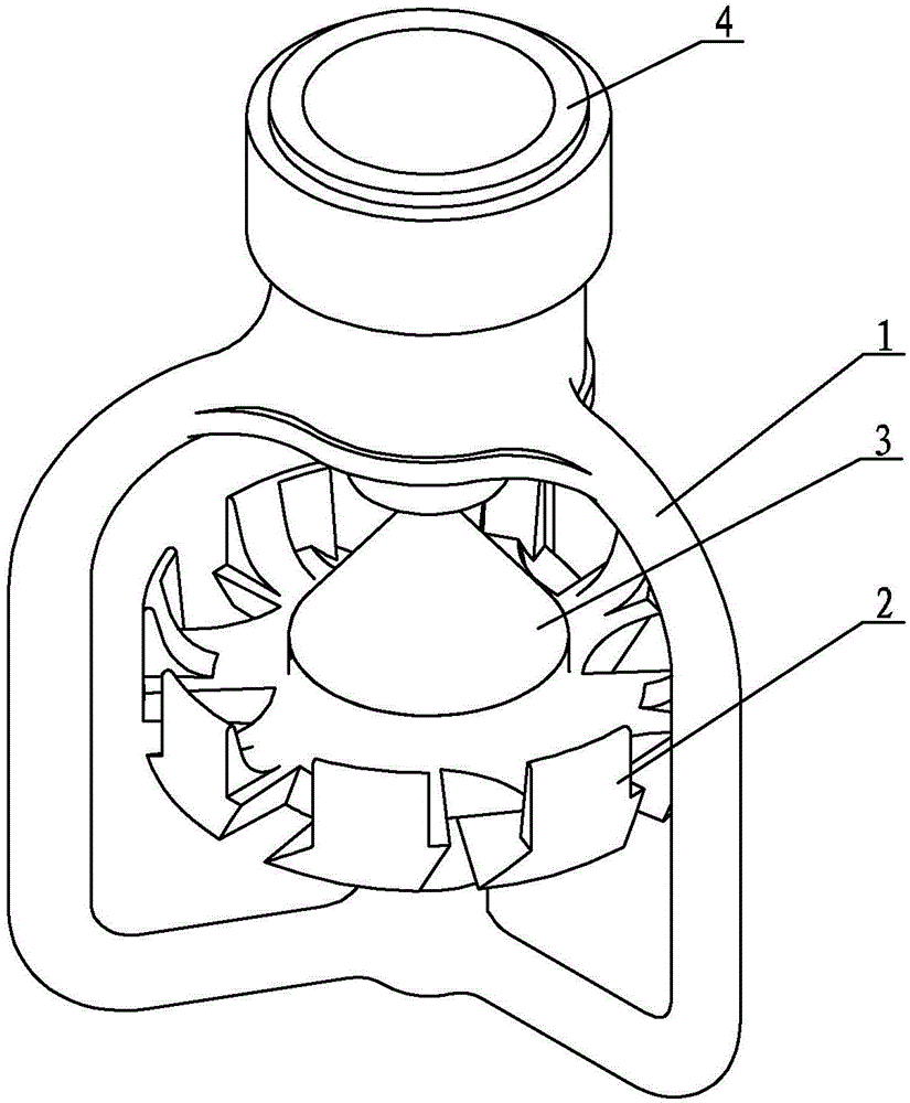
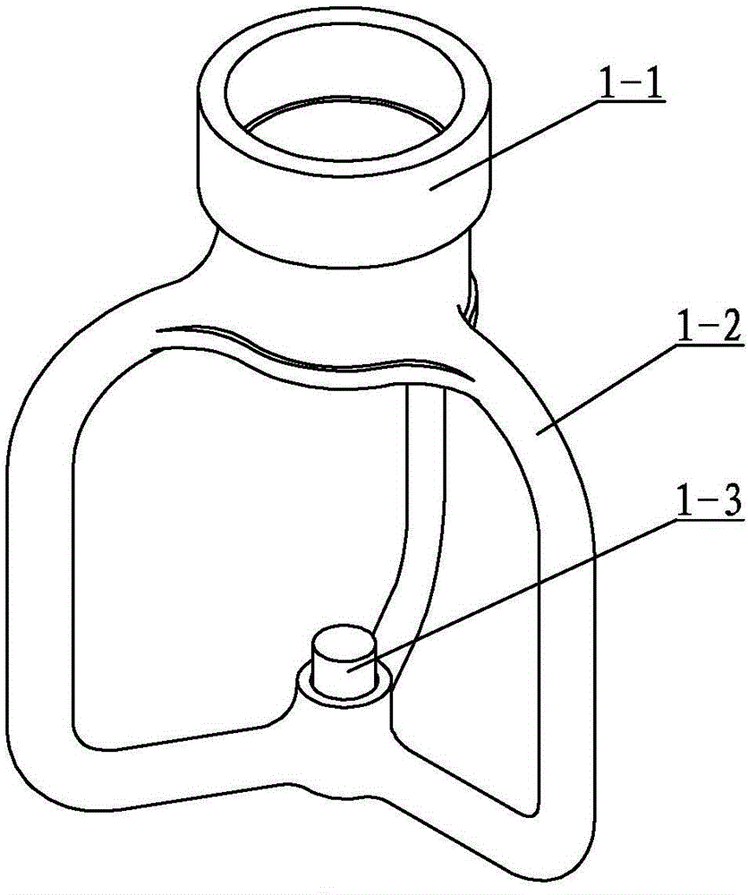
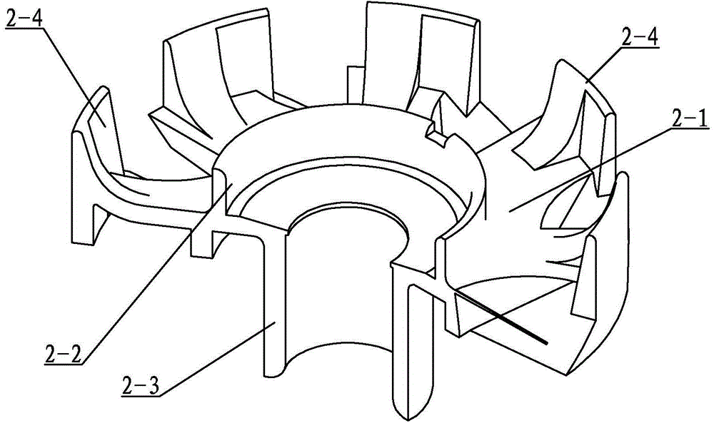
[0029] Specific implementation mode one: combine Figure 1 to Figure 6 Describe this embodiment, this embodiment comprises skeleton 1, impeller 2, water distributor 3 and water inlet pipe 4, and described skeleton 1 is made up of placement port 1-1, support frame 1-2 and support shaft 1-3, placement port 1-1 is set on the upper end of the support frame 1-2, the support shaft 1-3 is set on the lower end of the support frame 1-2, the placement port 1-1 is set coaxially with the support shaft 1-3, and the impeller 2 is composed of the disc 2-1, The upper ring 2-2, the shaft sleeve 2-3 and several blades 2-4 are composed, the upper ring 2-2 is located above the disc 2-1, and the shaft sleeve 2-3 is located below the disc 2-1, The upper ring 2-2, the disk 2-1 and the shaft sleeve 2-3 are coaxially arranged and made into one body, and the disk 2-1 is evenly arranged with several blades 2-4 along the edge, between two adjacent blades 2-4 There is a gap between them, and the side of ...

specific Embodiment approach 2

[0030] Specific implementation mode two: combination Figure 4 To illustrate this embodiment, the driving surface 2-4-1 of this embodiment is a slope inclined from the inside to the outside and from top to bottom, and the driving angle β of the driving surface 2-4-1 is 10° to 45° . The driving angle β is small, the slope of the driving surface 2-4-1 is large, the driving force is large, and the speed of the impeller is high; the driving angle β is large, the slope of the driving surface 2-4-1 is small, the driving force is small, and the speed of the impeller is low. Other components and connections are the same as those in the first embodiment.

specific Embodiment approach 3

[0031] Specific implementation mode three: combination Figure 4 The present embodiment will be described. The driving angle β of the present embodiment is 30°. The driving angle β is at this value, which makes the driving force and impeller speed high more reasonable. Other components and connections are the same as those in the second embodiment.


PUM


Abstract

The invention discloses a rotary splashing device, and relates to a cooling water splashing device of a cooling tower in order to solve the problems that according to an existing splashing device, outflow water is splashed out in the same plane in the axial direction, high resistance to air is generated in the splashing process, and circumferential water distribution evenness is poor. An impeller is composed of a disk, an upper round ring, a shaft sleeve and a plurality of blades, wherein the upper round ring is located above the disk, the shaft sleeve is located below the disk, the upper round ring, the disk and the shaft sleeve are coaxially arranged to be made into a whole, the blades are evenly distributed on the edge of the disk, a gap is reserved between every two adjacent blades, a driving face is arranged on the side, corresponding to the gap, of each blade, a first water splashing face is arranged on the other side of each blade, the plane between the top end of each first water splashing face to the lateral side of the corresponding blade is a second water splashing face, a third water splashing face and a fourth water splashing face are arranged on the radial inner surface of each blade, the shaft sleeve of the impeller is installed on a supporting shaft through a bearing, a water distributor is installed in the upper round ring of the impeller, and a water inlet pipe is installed in a placing opening. The rotary splashing device is used for spraying in the cooling tower.

Description

technical field [0001] The invention relates to a cooling tower cooling water splashing device, in particular to a rotary splashing device used in a cooling tower. Background technique [0002] The function of the cooling tower is to exchange heat between the cooling water carrying the waste heat and the air in the tower, so that the waste heat is transferred to the air and diffused into the atmosphere. Its working principle is that the cooling water with waste heat is distributed to the splashing device through the water distribution system (pipe type or trough type), and the splashing device breaks up the water into small water droplets, which are evenly sprinkled on the water spray packing, so that It is in full contact with the air to evaporate and dissipate heat. [0003] "Power Engineering Water Design Manual" (China Electric Power Publishing House, first edition, pages 685-687 in May 2005) puts forward specific requirements for the technical characteristics of the sp...

Claims


Application Information

Patent Timeline
IPC IPC(8): F28F25/06
Inventor 魏熙臣
Owner 魏熙臣
Why Eureka
Try Eureka