
Detecting method and system based on binocular camera for real-time vehicle speed

A binocular camera, vehicle speed detection technology, applied in the radio wave measurement system, the device used to measure the time required to move a certain distance, the re-radiation of electromagnetic waves, etc., can solve the problem of expensive infrared detection devices, increased complexity, and vehicle speed detection system failure etc.

Inactive Publication Date: 2014-11-19
SOUTH CHINA UNIV OF TECH
View PDF6 Cites 39 Cited by
  • Summary
  • Abstract
  • Description
  • Claims
  • Application Information

AI Technical Summary

Problems solved by technology

In the proposed binocular stereo vision vehicle speed detection system, an additional infrared detection device is required to detect the target vehicle. When multiple vehicles pass by the infrared detection device on a road at the same time, the vehicle speed detection system may fail, which has certain limitations.
At the same time, the infrared detection device with high precision and stable performance is expensive, which increases the initial investment and later maintenance costs
In addition, the height of the binocular camera from the road surface and the distance between the infrared detection device and the binocular camera need to be known in advance during use, which increases the complexity of the system.

Method used


Image

  • Detecting method and system based on binocular camera for real-time vehicle speed
  • Detecting method and system based on binocular camera for real-time vehicle speed
  • Detecting method and system based on binocular camera for real-time vehicle speed

Examples


Embodiment

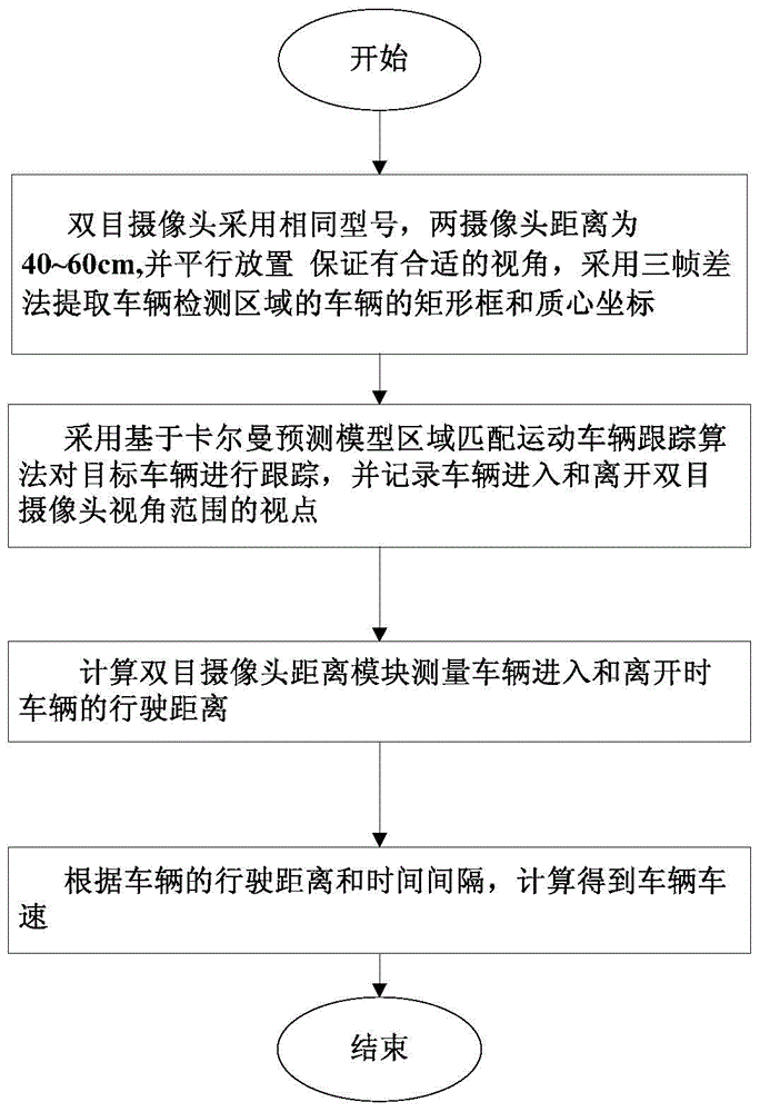
[0058] Such as figure 1 As shown, this embodiment discloses a real-time vehicle speed detection method based on binocular cameras, and the steps are as follows:

[0059] 1) Detect vehicles entering the viewing angle range through the binocular camera installed on the roadside: use the three-frame difference method to extract the rectangular frame and centroid coordinates of the vehicle entering the viewing angle range of the binocular camera, and use the Kalman prediction model area to match the moving vehicle tracking Algorithm to track the target vehicle;

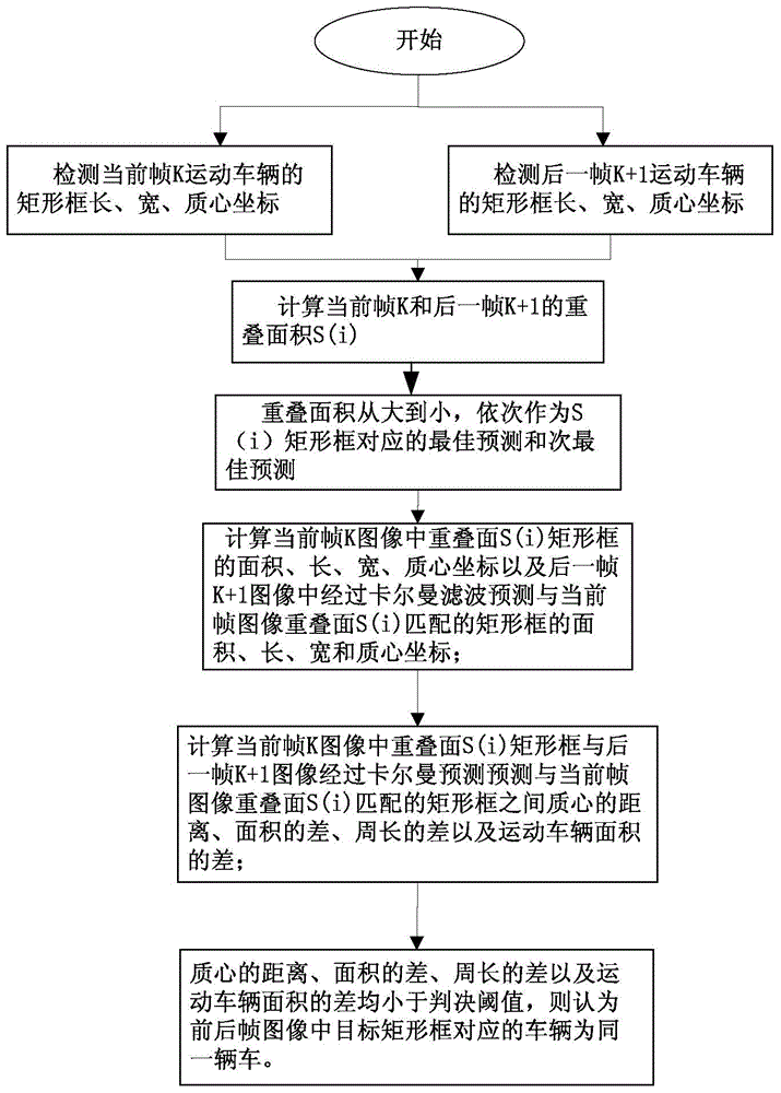
[0060] Such as figure 2 As shown, in this embodiment, the three-frame difference method is used to extract the rectangular frame and the center of mass coordinates of the target vehicle that enters the viewing angle of the binocular camera. The specific process is as follows:

[0061] 1-1) Perform 3×3 median filter preprocessing on the image sequence captured by the binocular camera; remove the image random noise. Reduce the c...


PUM


Abstract

The invention discloses a detecting method and system based on a binocular camera for real-time vehicle speed. The detecting method comprises the following steps: 1) extracting a rectangular frame and a barycentric coordinate entering a visual angle range of the binocular camera, and tracking a target vehicle; 2) recording the position and the time of a vehicle entering or leaving the visual angle range of the binocular camera; 3) pre-building a parallax depth chart of the binocular camera and a proportional relation chart of perpendicular lengths from viewpoints at the depths of the binocular camera to an optical axis and the pixel count of imagery; 4) acquiring parallax of the vehicle entering the viewpoints of the visual angle range of the binocular camera and leaving the viewpoints of the visual angle range of the binocular camera to obtain the perpendicular lengths from the viewpoints of an entering position or a leaving position of the vehicle to the optical axis; 5) calculating a traveling distance between the viewpoints of the entering position and the leaving position of the vehicle, and obtaining the vehicle speed of the vehicle according to the traveling distance and the time of the vehicle. The detecting method and system have the advantages that the speed measuring precision is high, and speed measurement can be performed on multiple vehicle objectives on multilane at the same time.

Description

Technical field [0001] The invention relates to a vehicle speed detection method, in particular to a real-time vehicle speed detection method and system based on binocular cameras. Background technique [0002] With the development of society and the continuous improvement of people's living standards, the use of motor vehicles has become one of the important means of transportation. With the continuous increase in the amount of motor vehicles put into use, how to effectively realize the management and statistics of motor vehicles plays an important role in road traffic safety and management. The detection of motor vehicle speed is an important aspect of traffic management. [0003] At present, radar, laser or induction coil are mainly used to detect vehicle speed on the road. The above methods have been developed relatively mature, but there are certain limitations in the use process. The speed measurement method based on the ground-sensing coil has the advantage of obtaining t...

Claims


Application Information

Patent Timeline
IPC IPC(8): G01P3/68
Inventor 冯颖张欣杜娟邹超洋
Owner SOUTH CHINA UNIV OF TECH
Learn More