Ripple compensation control circuit for DC-DC converter

A technology of DC-DC and ripple compensation, which is applied in control/regulation systems, DC power input conversion to DC power output, instruments, etc., can solve stability problems and other problems, and achieve reduction of overall cost, reduction of circuit power consumption, The effect of improving the accuracy of the circuit

Inactive Publication Date: 2014-11-19
UNIV OF ELECTRONICS SCI & TECH OF CHINA
View PDF3 Cites 44 Cited by
  • Summary
  • Abstract
  • Description
  • Claims
  • Application Information

AI Technical Summary

Problems solved by technology

[0004] The purpose of the present invention is to provide a ripple compensation control circuit for DC-DC converters aiming at the current stability problems brought by low ESR capacitors to COT control systems

Method used


Image

  • Ripple compensation control circuit for DC-DC converter
  • Ripple compensation control circuit for DC-DC converter
  • Ripple compensation control circuit for DC-DC converter

Examples


Embodiment Construction

[0013] The present invention is described in detail below in conjunction with accompanying drawing

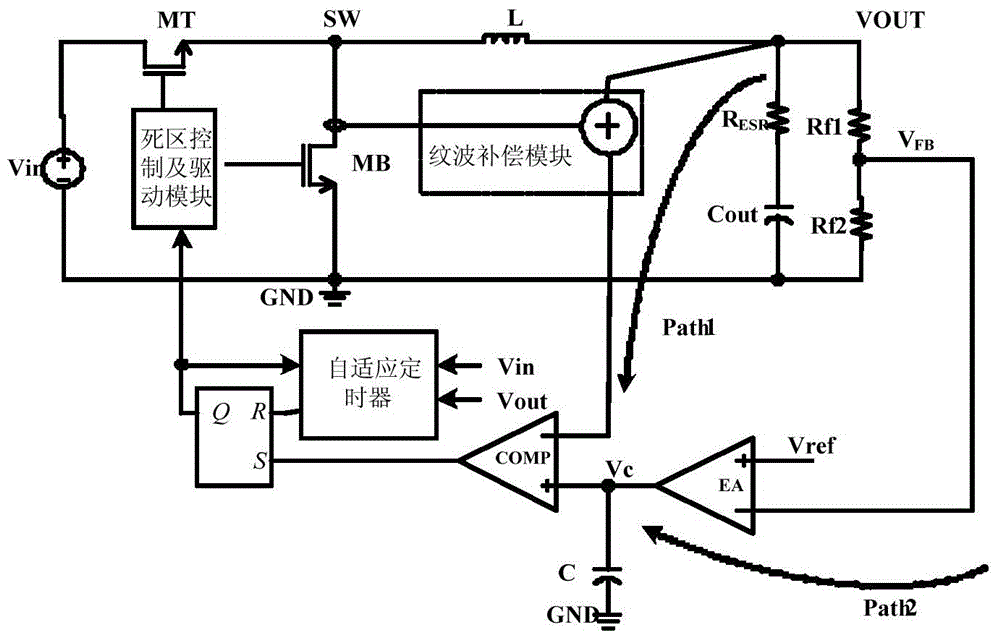
[0014] Such as figure 1 As shown, the ripple compensation control circuit for the DC-DC converter of the present invention includes a first power tube MT, a second power tube MB, a dead zone control and drive module, a ripple compensation module, an adaptive timer, RS flip-flop, operational amplifier, inductor L, first resistor Rf1, second resistor Rf2, third resistor R ESR , the first capacitor Cout, the second capacitor C and the error amplifier; wherein, the drain of the first power transistor is connected to the power supply, its gate is connected to the output end of the dead zone control and drive module, and its source passes through the inductor L, the first The resistor Rf1 and the second resistor Rf2 are connected to the ground; the drain of the second power tube MB is connected to the connection point between the source of the first power tube MT and the inductor L,...


PUM


Abstract

The invention belongs to the technical field of electronic circuits, and particularly relates to a ripple compensation control circuit for a DC-DC converter. The benefit of the invention is that an internally integrated feedback ripple compensation circuit is designed to free a COT (constant on time) control system from the dependence on output capacitance ESR (equivalent series resistance) and to widen the optional range of output capacitance cells, thereby ensuring stable operation of the system. The on-chip ripple compensation technology is adopted to solve the problem that the traditional off chip compensation method has the disadvantages of complex structure and large occupied area, thereby reducing the total cost of a converter, expanding the applicable range of circuits, improving circuit accuracy and reducing circuit consumption. The invention is particularly suitable for a DC-DC converter.

Description

technical field [0001] The invention belongs to the technical field of electronic circuits, and in particular relates to a ripple compensation control circuit for a DC-DC converter. Background technique [0002] Compared with the traditional voltage mode control or current mode control, the control system based on output ripple has the characteristics of faster transient response and simple control loop, especially the ripple control based on constant on-time The potential of adaptive constant frequency characteristics has attracted much attention. However, due to the capacitive characteristics of the output capacitor, the output voltage has a certain phase lag characteristic with respect to the current information, so for all converter systems that directly use the output ripple for control, sufficient output capacitor ESR (equivalent series resistance ) value is a necessary condition for system stability. When the ESR is small, the constant on-time controlled switching c...

Claims


Application Information

Patent Timeline
Patent Type & Authority Applications(China)
IPC IPC(8): H02M1/15H02M3/155
Inventor 周泽坤冯捷斐刘德尚石跃艾鑫王卓张波
Owner UNIV OF ELECTRONICS SCI & TECH OF CHINA
Why Eureka
Try Eureka