Hydraulic pipe bending device

A pipe bending device and hydraulic technology, which is applied in the field of hydraulic pipe bending devices, can solve problems such as damaged pipe fittings, slow processing speed, and substandard processing of pipe fittings, and achieve the effects of convenient disassembly and installation, reduced maintenance costs, and increased practicability

Active Publication Date: 2014-11-26
中国电建集团河北工程有限公司
View PDF5 Cites 8 Cited by
  • Summary
  • Abstract
  • Description
  • Claims
  • Application Information

AI Technical Summary

Problems solved by technology

[0002] The hydraulic pipe bender relies on the hydraulic cylinder to drive the linkage device to bend the pipe. It is divided into two types: the top bending type of the oil cylinder and the chain type driven by the oil cylinder. The advantage of this type of pipe bending machine is that the processing speed is fast and it is suitable for mass production. The disadvantage is the stability. Poor, high maintenance cost, and oil leakage of hydraulic cylinder often occurs. When the hydraulic cylinder is pushed, it is easy to cause damage to the pipe fittings due to excessive thrust or small thrust resulting in substandard processing of pipe fittings; while mechanical pipe benders It is based on the principle of mechanical gears and levers to bend pipes. It is divided into two types: electric pipe benders and manual lever pipe benders. The advantages of this type of pipe bending equipment are simple operation, convenient maintenance and low cost, long machine life and high processing accuracy. , and the equipment is small and mobile, the disadvantage is that the processing speed is slow and the efficiency is low

Method used


Image

  • Hydraulic pipe bending device

Examples


Embodiment

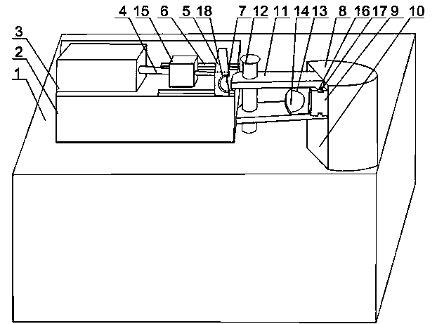
[0020] Such as figure 1 As shown, a hydraulic pipe bending device of the present invention includes a bracket 1, on which a pipe bending column 8 and a boss 2 are installed, the boss 2 is arranged on one side of the pipe bending column 8, and the hydraulic cylinder 3 is installed On the boss 2, a connecting rod 4 is installed on the output end of the hydraulic cylinder 3, and the end of the connecting rod 4 is connected with a push plate 5, and a guide rail 6 is installed on the support 1, and the push plate 5 is slidably arranged on the guide rail 6, the push plate 5 is provided with a U-shaped groove 7, the side of the elbow column 8 facing the hydraulic cylinder 3 is provided with a rectangular section 10, and a fixed block 9 is provided at the middle and upper part of the rectangular section 10. The upper and lower sides of the fixed block 9 are respectively provided with a limit plate 11, the limit plate 11 is placed outside the end of the U-shaped groove 7, the end of th...


PUM


Abstract

The invention discloses a hydraulic pipe bending device. The hydraulic pipe bending device comprises a positioning block, wherein the positioning block is fixedly installed on a support and provided with a positioning hole, the diameter of a connecting rod gradually decreases in the axis direction from left to right, the connecting rod penetrates through the positioning hole and is connected with a propelling plate, a pressure sensor and a controller which are connected with each other are installed on the inner wall of the positioning hole, and the controller is connected with a hydraulic cylinder; bosses are arranged at the bottom of a limiting plate, the upper side and the lower side of a fixing block are provided with trapezoidal grooves meshed with the bosses respectively, and the limiting plate is fixed to the trapezoidal grooves through bolts. The hydraulic pipe bending device is simple in structure, and the propelling plate is arranged on a guide rail in a sliding mode so that stable movement of the propelling plate can be ensured; the mode of bolt connection or movable connection through sliding arrangement is adopted for the overall structure of the device, so that the hydraulic pipe bending device is convenient and fast to assemble and disassemble, and the maintenance cost of the device is effectively reduced.

Description

technical field [0001] The invention relates to a pipe bending device, in particular to a hydraulic pipe bending device. Background technique [0002] The hydraulic pipe bender relies on the hydraulic cylinder to drive the linkage device to bend the pipe. It is divided into two types: the top bending type of the oil cylinder and the chain type driven by the oil cylinder. The advantage of this type of pipe bending machine is that the processing speed is fast and it is suitable for mass production. The disadvantage is the stability. Poor, high maintenance cost, and oil leakage of hydraulic cylinder often occurs. When the hydraulic cylinder is pushed, it is easy to cause damage to the pipe fittings due to excessive thrust or small thrust resulting in substandard processing of pipe fittings; while mechanical pipe benders It is based on the principle of mechanical gears and levers to bend pipes. It is divided into two types: electric pipe benders and manual lever pipe benders. Th...

Claims


Application Information

Patent Timeline
Patent Type & Authority Applications(China)
IPC IPC(8): B21D7/08
Inventor 朱文远周尚燕胡建中
Owner 中国电建集团河北工程有限公司
Why Eureka
Try Eureka